1Technical Chemistry I and Center for Nanointegration Duisburg-Essen (CENIDE), University of Duisburg-Essen, Universitätsstraße 7, 45141 Essen, Germany
2Graduate School of Engineering, Hokkaido University, Sapporo, Japan
Guest Editor: G. Mínguez-Vega Beilstein J. Nanotechnol.2026,17, 1582–1595.https://doi.org/10.3762/bjnano.17.108 Received 10 Jul 2026,
Accepted 12 Oct 2026,
Published 10 Nov 2026
Monodisperse, spherical sub-micrometer particles with clean, smooth surfaces are key materials used as composite reinforcements, abrasives, and tribological additives, but remain synthetically challenging to produce. Pulsed laser melting in liquids (LML) is an environmentally friendly, emerging route for producing such particles. However, demonstrations have so far been limited to batch reactors, which are difficult to scale up to industrial production. Here, we extend laser melting in liquids to a continuous flat jet flow-through reactor in which boron carbide composite nanoparticles (B4CC) dispersed in ethanol are fed perpendicular to a nanosecond pulsed high-power ultraviolet laser beam; this is complemented by additional experiments employing pristine boron carbide. We elucidate how flow conditions and the application of modern high-repetition-rate lasers alter particle formation pathways. Characterization of B4CC, irradiated at fluences of 45–135 mJ·cm−2, by transmission electron microscopy and dynamic light scattering, evidences the formation of a bimodal size distribution of spherical particles with mean diameters of ≈50 and ≈100 nm, verifying the parallel occurrence of isochoric reshaping and an aggregation–melting–fusion mechanism. While the smaller particle size fraction formed in accordance with thermal equilibrium calculations, the second size mode, derived from a multistep aggregation–melt–fusion pathway, was significantly smaller than predicted. Systematic variation of the number of laser pulses per unit volume (PPV) from 1 to 16 by tuning the interpulse delay (τIP) from 1.4 to 0.1 ms revealed an initial increase of the mean diameter of the second mode with PPV, reaching maximum size at 4 PPV. Interestingly, at higher PPV, further particle growth is arrested, probably due to an interplay between low particle mass concentration and shorter τIP limiting the number of aggregation–melt–fusion steps, indicating kinetically controlled particle formation pathways. If the laser fluence is increased to 180 mJ·cm−2, laser fragmentation in liquid prevails, and small mass fractions of ultrasmall nanoparticles (approx. 2 nm) are formed, which constitutes the upper limit of the LML process window. Overall, at the example of the ultrahard material boron carbide, difficult to process by other methods into perfect spheres, kinetically controlled LML in a flat jet flow-through reactor gives access to nanostructures in a size range previously unattainable by laser processing, establishing the basis for upscaling production in liquid flow with matched laser pulse numbers.
Hard ceramic sub-micrometer spheres (SMSs) represent a class of materials with exceptional mechanical and chemical stability, rendering them indispensable for emerging technologies [1,2]. Their relevance spans a wide range of applications, including composite reinforcements [3-5], abrasives [6-8], drilling materials [9,10], and solid lubricant systems [11-13]. Hardness, crystallinity, and particle size distribution are the major physicochemical properties that determine the performance of ceramic SMSs in these applications; these properties are primarily dictated by the synthesis route [14,15]. Conventional synthesis methods, however, face substantial limitations in meeting the stringent purity, crystallinity, and particle size requirements to tune the SMSs to their corresponding application. Among ceramics, boron carbide (B4C) is particularly noteworthy due to its outstanding hardness, ranking among the highest on the Mohs scale (about 9.5) [16]. Despite its favorable characteristics, boron carbide synthesis and processing pose considerable challenges. While several synthesis routes have been explored for boron carbide nanoparticles (NPs) and SMSs, each presents inherent limitations regarding crystallinity, dispersibility, or size control. Solvothermal and wet-chemical approaches typically yield amorphous or poorly crystalline products that exhibit pronounced aggregation [17,18], whereas chemical vapor deposition [19-21] can produce highly crystalline B4C but suffers from formation of polydisperse particles and limited scalability. As a result, the fabrication of well-dispersed, crystalline, and smooth-surfaced B4C spheres with monomodal size distributions remains challenging. This difficulty is further amplified during particle comminution, as the pronounced hardness and intrinsic brittleness of B4C severely hinder mechanical size reduction and homogenization. Aligned with the chemical industry’s ongoing transition toward greener and more sustainable manufacturing paradigms [22,23], pulsed laser melting in liquid (LML) has emerged as an attractive approach for NP processing [24]. The technique relies solely on electrical energy (to create the laser beam), which can be sourced renewably. But also the role of the liquid (which in the case of ethanol may not be fully recyclable) needs to be considered. For more details on LML-specific sustainability aspects, we refer to the recent assessment of the four variants of laser synthesis and processing of colloids regarding the twelve green chemistry criteria [25]. Ethanol was selected as the liquid medium because aqueous processing may promote oxidation [26] and hydrolysis of boron-containing species under the high-temperature conditions generated during laser processing; in contrast, ethanol provides a less oxidizing environment but may additionally generate transient carbonaceous species through solvent decomposition [27]. To date, boron carbide SMSs produced by LML of feedstock NPs have been exclusively generated based on boron NPs, which are transformed into boron carbide SMSs due to the incorporation of carbonaceous radicals from solvent decomposition [24]. This kind of reactive LML relies on a complex design where physical particle melting and chemical reactions have to be controlled in parallel. It necessitates multipulse processing and irradiation times up to 60 min in batch reactors. A simpler and potentially more robust LML synthesis route where B4C SMSs are formed directly from B4C NPs has rarely been investigated, mainly because synthesizing B4C NP starting materials is more challenging, and commercial availability is limited [28]. Direct processing of pre-formed B4C NPs offers the advantage of bypassing the kinetically demanding incorporation of carbon into molten boron, which is particularly relevant for short-residence-time, continuous high-throughput processing. In this way, the use of B4C feedstock can facilitate the formation of stoichiometric and phase-pure B4C spheres without requiring an additional carbonization step during laser processing, provided that the starting material already meets the required phase-purity specifications. Previous investigations demonstrated that four pulses are sufficient to induce SMS formation under batch conditions using boron [29]. However, this pulse number proves inadequate for a quantitative conversion of elemental boron to boron carbide. Higher-repetition-rate lasers would facilitate higher-pulse-number applications in both batch and flow-through reactors. However, to date, almost all LML-based approaches have been conducted in batch or guided-flow configurations coupled with Nd:YAG lasers operating at low repetition rates (typically around 10 Hz) [24,28,30,31]. These systems inherently limit throughput and scalability and are hardly suitable for the scale-up of boron carbide SMS synthesis by LML [29]. Even existing guided-flow reactors have deep liquid paths and turbulent back-mixing, leading to severe optical shielding, non-uniform fluence profiles, and undefined irradiation histories per particle. The integration of a high-repetition-rate laser into a continuous-flow flat jet LML platform thus fundamentally advances previous LML approaches. Although laser systems with high pulse energy allow for a significant increase in the irradiated volume at equivalent fluence, this enlargement causes pronounced shielding effects in the irradiated volume. These effects occur when particles or created bubbles absorb or scatter the laser beam, leading to steep fluence gradients within the irradiated volume, strongly influencing the LML process and SMS quality. Here, regions experiencing higher fluence yield different particle sizes or morphologies compared to areas exposed to lower fluence. These non-uniform energy distributions compromise control over particle size and homogeneity, which is critical for scalability. To overcome these obstacles, scale-up approaches necessitate switching from large-volume batches to smaller irradiated volumes realized in continuous liquid-flow reactors, where throughput is controlled by the volume flow rate [32].
The current state of the art in scaled up laser synthesis and processing of colloids is based on the utilization of high-power lasers (up to 400 W) operated at kilohertz-to-megahertz repetition rates, frequently combined with advanced continuous liquid-jet setups applicable for laser fragmentation in liquids (LFL) [33-35] and pulsed laser defect engineering in liquids [36,37], where throughputs of several grams per hour have been realized [34,37,38]. Such advanced laser-processing setups have not been used in the context of LML. There, they could dramatically increase the number of laser pulses available for continuous processing, while maintaining a stable interaction zone that minimizes self-focusing and defocusing effects. However, a critical challenge at such high repetition rates arises from heat buildup [39]. If the pulse sequences are too fast, the particle will not fully cool down before the next pulse hits it. This may cause a further increase in the particle’s temperature by heat accumulation, which promotes fragmentation [40]. These thermally driven nonlinearities, furthermore, fundamentally impair uniform and controlled formation of SMSs as they introduce fluctuations in aggregation kinetics [41,42] and transport of reactive intermediates [43]. Such considerations, however, reveal an intrinsic mismatch between simplified theoretical models and experimental observations. The model proposed by Koshizaki et al. predicts cooling times for molten SMSs of the order of milliseconds, rationalizing heat accumulation onset at repetition rates exceeding 400 Hz [40]. In contrast, recent studies report cooling rates for SMS-regime particles approaching 109 K·s−1[44-46], implying that an SMS or molten aggregate at 4000 K returns to ambient temperature within about 4 μs. This estimate, however, reflects only the maximum cooling rate at the onset of heat transfer, when the temperature difference between particle and liquid is largest. As the particle cools, the temperature gradient and thus the instantaneous cooling rate decrease continuously. Consequently, the total cooling time to room temperature can be expected to be roughly one order of magnitude larger, corresponding to an effective average cooling rate of about 108 K·s−1. Nonetheless, LML in batch setups demonstrates the formation of substantially smaller NP fractions already at 0.4 kHz, corresponding to cooling times of about 2.5 ms and indicating fragmentation under ostensibly thermally benign conditions [40]. This unresolved discrepancy, spanning nearly three orders of magnitude between theory (particle cooling time) and experiment (time between two pulses), likely originates from batch configuration characteristics that introduce unmodeled thermal and hydrodynamic effects. Such effects can be disentangled by implementing a flat jet flow-through reactor into LML research, where fluence deviations are minimal and the number of pulses per volume (PPV) can be precisely tuned [36]. Thereby, LML processes may be meticulously mechanistically explored and further adapted to function in high-throughput, high-power, and high-repetition-rate laser setups.
In the current study, we examine the extent to which steady-state high-power laser processing in flowing ethanol can be used for the scalable synthesis of boron carbide SMSs. This experimental design may be further utilized to study particle formation pathways under kinetic control, contrasting thermodynamic equilibrium conditions during batch processing, well described and established in the literature. Hence, in contrast to the state-of-the-art LML, we utilize the following methodological innovations: (i) boron carbide composite (B4CC) as feedstock material instead of boron, aiming at faster processing with a lower number of laser pulses, (ii) a thin flat jet flow-through reactor that minimizes fluence gradients along the laser beam path, which enables uniform flow conditions and a precise setting of the PPV for the whole processed volume, and (iii) a high-repetition-rate laser (10 kHz) with a hundred times lower pulse intervals, potentially shorter than the particle cooling time between pulses.
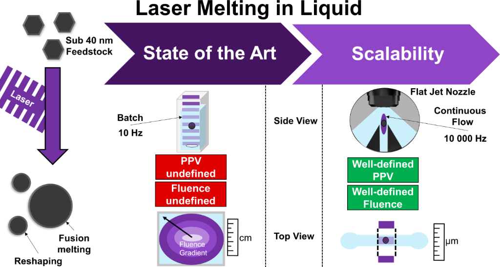
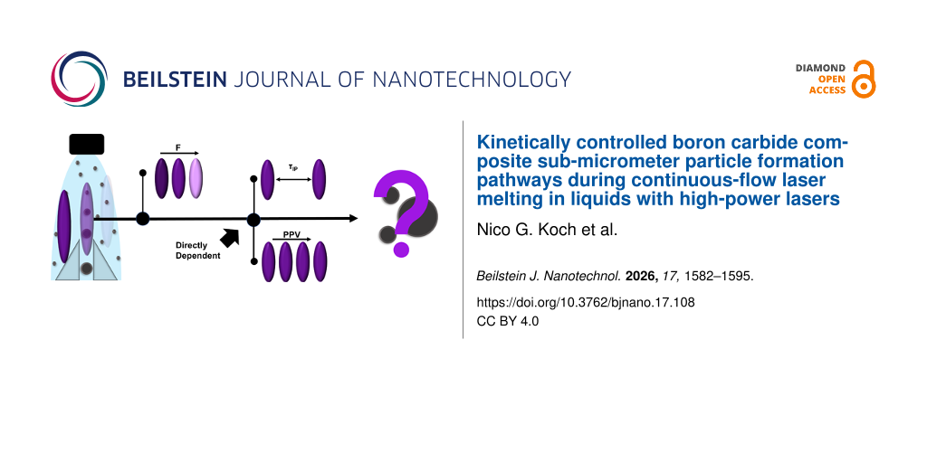
Transmission and scanning electron microscopy (TEM and SEM) are employed to evaluate morphological changes, while dynamic light scattering (DLS) provides quantitative insight into size distributions. Together, these analyses elucidate the relationship between laser parameters, SMS formation mechanisms, and the resulting material properties in the underexplored kinetically controlled particle formation regime during LML. Ultimately, this study seeks to bridge the conceptual divide between fundamental laser–matter interaction physics and the practical requirements of scalable SMS production. By demonstrating the feasibility of a high-frequency UV-nanosesond-LML process within a flat jet geometry, the work establishes a pathway for future mechanistic studies and process optimization. A demonstrative scale-up emphasizes the application relevance of this methodology and its potential contribution to sustainable nanomaterials manufacturing if fully optimized. The general concept and the design of the study are illustrated in Figure 1.
Figure 1:
General concept of the LML transition to high-power flow-through setups coupled with a flat jet approach. Left: The two particle formation pathways of isochoric reshaping and aggregation–melting–fusion, both simultaneously occurring during LML. Middle: General shortcomings of established batch setups for LML are characterized by undefined irradiation conditions (fluence and PPV). Right: Schematic setup of the flat jet flow-through setup used in this work to overcome the limitations of batch processing.
Figure 1:
General concept of the LML transition to high-power flow-through setups coupled with a flat jet app...
The B4CC particles (mean particle diameter of 40–80 nm according to the manufacturer) were purchased from Nanografi [47] and dispersed in absolute ethanol (99.8%, VWR) using a Hielscher UP200ST [48] sonotrode operated at 100 W for 10 min. For purification, the suspension was subsequently filtered through a syringe filter (76479-060, VWR) to remove residual large feedstock particles with a cutoff above 100 nm. For each experiment, 100 mL feedstock suspension was prepared, with a B4CC mass concentration of 250 mg·L−1. Since the LML process was operated as a closed-loop recirculation process without intentional mass removal, the overall particle concentration remained constant throughout laser processing. Solvent evaporation was negligible under the employed conditions, and any minor evaporated solvent was condensed within the closed flow system. Laser processing was conducted using a UV nanosecond laser system (Trumpf TruMicro 8340, 400 Watt at 10 kHz, 18 ns, 343 nm) integrated into a flat jet setup developed within the research group (Supporting Information File 1, Figure S1). The average laser power was monitored using the integrated measurement tool of the Trumpf laser system. The laser beam was focused to a spot size of 0.12 cm2 (2 mm by 8 mm) using a Thorlabs cylindrical lens with a focal length of 500 mm. The resulting fluence values calculated from this profile may be subject to systematic error due to the spot size measurement. Based on the specifications of the beam profiling camera (Ophir SP932U), the estimated systematic measurement uncertainty of the beam diameter is 2%. However, as all measurements were performed within an identical experimental setup, this potential offset remains constant and does not affect the comparative validity or relative trends reported in this study. The liquid jet was generated by a 90° nozzle (NF90303BSP, BETE Spray Technology), producing a laminar liquid layer with a thickness of 35 µm as determined by UV–vis extinction spectroscopy (Flame, Ocean Optic, Supporting Information File 1, Figure S2). This configuration eliminates both laser refraction at the air–liquid interface and liquid back-mixing phenomena, thus ensuring reproducible laser–matter interactions under defined optical and hydrodynamic conditions. Quantitative evaluation of the medium’s absorption behavior was performed using the Beer–Lambert's law, enabling the correlation of optical absorbance with solute concentration for precise process control. To selectively capture the laser-excited volume fraction, a custom-built mechanical separation unit of 3 mm redirects unirradiated fractions into a closed-loop recirculation pathway, thereby efficiently using the feedstock material (Supporting Information File 1, Figure S1). The separation knives need to have a safety distance (0.5 mm) from the laser beam edge, so that only 66% of the volume collected downstream was processed by LML (2 mm laser and 3 mm separation width). The experiments at varying fluence were performed at a constant repetition rate of 10 kHz and a laser power between 200 and 400 W and 16 PPV. The volumetric flow rate of the treated suspension was maintained at 20 mL·min−1 using an Ismatec REGLO-Z pump. The calculated Reynolds number of 147 (see Supporting Information File 1 for further information) and low pump pulsation indicate operation within a non-turbulent regime, ensuring reproducible layer thickness and minimal flow fluctuations. For PPV studies, an integrated divider module was employed to adjust the laser output repetition rate (0.7–10 kHz) and thereby the PPV within a range from 1 to 16. This results in interpulse delays from 0.1 to 1.4 ms (see Supporting Information File 1, Section S4, Table S1).
X-ray photoelectron spectroscopy
To prepare the sample for X-ray photoelectron spectroscopy (XPS) analysis, the powdered material was pressed directly onto an indium film substrate. XPS measurements were conducted using a JEOL JPS-9200 spectrometer equipped with a monochromate Al Kα X-ray source. An electron neutralizer was utilized during data acquisition to compensate for surface charging effects. Spectral deconvolution and quantitative analysis were performed using standard fitting procedures. A Shirley-type background subtraction was applied to isolate the core-level signals. Peak fitting was carried out using a mixed Gaussian–Lorentzian line shape, where the Gaussian-to-Lorentzian mixing ratio was treated as an adjustable parameter during the fitting process.
Electron microscopy
To prepare the electron microscopy samples, the NP suspensions were concentrated using a centrifuge (Hettich Micro 220) with a nominal cutoff of 50 nm. The collected particles were subsequently washed three times with high-purity ethanol under identical centrifugation conditions to remove residual impurities originating from thermal ethanol decomposition. For transmission electron microscopy (TEM) analysis, 5 µL of the purified suspension was deposited onto a carbon-coated copper TEM grid, whereas for scanning electron microscopy (SEM), the suspension was dripped onto a polished silicon wafer. In both cases, the solvent was allowed to evaporate under ambient conditions. TEM imaging was carried out using a JEOL JEM 1400 Plus operated at 200 kV, while SEM characterization was conducted with a Thermo Scientific Magna Ray WDS Spectrometer. Image analysis and particle size evaluation were performed using the Fiji software package, measuring at least n = 250 particles.
Dynamic light scattering
Dynamic light scattering (DLS) measurements were conducted using a Zetasizer ZS90 (Malvern Instruments). The optical transmission of each sample was adjusted to approximately 70% using anhydrous ethanol as the solvent. A volume of 5 mL of the resulting suspension was transferred to a quartz cuvette, and measurements were performed in backscattering mode at 173°. The sample temperature was maintained at 25 °C throughout the experiment. To ensure statistical reliability, each sample was measured in triplicate, with three measurement cycles per replicate.
X-ray diffraction
X-ray diffraction (XRD) analysis was performed using a Bruker D2 Phaser benchtop diffractometer equipped with Cu Kα radiation (λ = 1.54056 Å). Approximately 100 mg of powdered samples were loaded onto a spinner reflection stage for enhanced angular reproducibility. The feedstock B4CC powder was analyzed directly as received from the commercial manufacturer without further treatment. For the laser-treated samples, the processed nanoparticle dispersion was collected after LML processing, concentrated by centrifugation, and dried at 60 °C to obtain the powder required for XRD analysis. Data were acquired over a 2θ range of 5–90° at a step size of 0.01214° and a step time of 3.6 s per step.
Thermogravimetric analysis
Thermogravimetric analysis (TGA) was performed using a Shimadzu TGA-50 thermal analyzer. The solid sample was weighed directly into an alumina crucible with an initial sample mass between 3 and 5 mg. Measurements were conducted under a nitrogen/oxygen atmosphere with a continuous purge flow rate of 20 mL·min−1. The temperature program consisted of dynamic heating from room temperature (approx. 25 °C) to a maximum temperature of 1000 °C at a constant heating rate of 25 °C·min−1. Sample mass loss and the corresponding derivative thermogravimetric signal were recorded continuously throughout the temperature range.
Results and Discussion
Feedstock nanoparticle characterization
To investigate the transferability of the LML process to continuous flow in a flat jet, a thorough characterization of the feedstock NPs is essential. To this end, we analyzed the feedstock particles by XRD, XPS, and TGA, verifying that we work with a boron carbide composite (B4CC) containing 21 wt % of boron carbide, as well as fractions of graphitic carbon and boron oxide. However, as carbon does not form stable SMSs at atmospheric pressure, it evaporates at 3642 °C [49], we can assume that SMSs formed from B4CC are mainly composed of B4C, although fractions of B or B2O3 in the particles cannot be excluded. As the SMSs generated by LML from pure B4C show similar particle diameters and shapes (Supporting Information File 1, Figure S3), we can assume that the herein used B4CC is suitable for mechanistic studies of LML (Supporting Information File 1, Section S2). Although the two feedstock materials have markedly different crystal structures, XRD analysis shows that their response is similar after LML. Notably, all diffraction features attributable to boron oxide disappear after processing, suggesting complete removal rather than reduction below the detection limit. This transformation occurs regardless of the initial crystallographic state, demonstrating that oxide formation is not only suppressed, but also effectively eliminated under the applied LML conditions, probably attributed to reductive environments frequently reported during LML in organic solvents [27]. To explain why we used B4CC feedstock rather than the B4C reference, we need to examine the particle size distribution of both (Supporting Information File 1, Figure S3). As we wanted to obtain scientific results based specifically on the aggregation–fusion–melting process, the broader particle size distribution of the B4C resulted in overlap between aggregation, melting, fusion, and isochoric reshaping. Therefore, although it is a composite, we used the B4CC due to its narrower size distribution and overall smaller mean particle diameters in the feedstock powder.
Fluence study
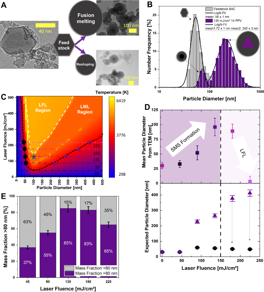
TEM analysis of the B4CC feedstock particles predominantly shows a hexagonal morphology according to the manufacturer’s specifications [47], as validated in Figure 2A. It is noteworthy, however, that particles smaller than 40 nm do not consistently possess a perfect hexagonal shape; some display rounded edges, though they remain distinctly non-spherical. The initial particle diameter distribution follows a characteristic log-normal profile, confirmed by TEM (Supporting Information File 1, Figure S5). The mean value from TEM is about 30 nm with a standard deviation of ±12 nm. These findings align with the manufacturer’s specifications, which indicate particle diameters in the range of 40 to 80 nm. The observed shift towards smaller particles below 40 nm is primarily attributed to the feedstock suspension purification steps described in the Experimental section. This initial characterization establishes a reliable baseline, enabling unambiguous attribution of any subsequent structural or morphological changes to laser–material interactions during the LML process. Owing to the inherent mechanisms of laser–particle interactions described by the heating–melting–evaporation (HME) model established by Koshizaki et al. for LML [50,51], the LML treatment is expected to yield a bimodal particle size distribution. According to this model, a given fluence has two particle size values in the bathtub-shaped fluence–diameter diagram (reaching the melting onset temperature). The feedstock particle size is already in the range of the first intersection (at the smaller size), but the formation of significantly larger molten spheres of the second melting-onset size would require the particles to fuse. This means that the smaller population arises from surface reshaping of pre-existing particles (including smaller agglomerates), while the larger sizes may only originate from aggregation–melting–fusion, as illustrated in Figure 2A. The corresponding bimodal size distribution pattern is corroborated by the DLS data in Figure 2B, where two distinct peaks can be assigned to the respective SMS sizes depicted in Figure 2A. TEM analysis also reveals a bimodal size distribution with a higher particle density (n = 2500) compared to Figure S5 (Supporting Information File 1).
Figure 2:
(A) Schematic representation of the LML concept, illustrating the transformation of irregular feedstock NPs into fusion-formed spherical SMSs and isochorically reshaped NPs, complemented by representative TEM micrographs of both feedstock particles and resulting SMSs. The corresponding number-weighted hydrodynamic size distributions determined by DLS (B) exemplify the evolution from the initial NPs to a bimodal distribution after LML at 135 mJ·cm−2 and 16 PPV with a graphic illustration of educt isochoric remelting (circle) and fusion melting (triangle). (C) Prediction of the LFL and LML regimes using the extended HME model, with a marked fluence series of 45, 90, 135, 180, and 225 mJ·cm−2, with the modeled reshaping products indicated by black circles and the expected SMS diameters after fusion-melting indicated by purple triangle markers. The dashed black line marks the start of the LML region, whereas the dashed white line marks the start of the LFL region. The star denotes the observed mean particle size for both B4CC and the B4C reference (see Supporting Information File 1, Section S3). (D) Quantitative evaluation of TEM-derived (from Supporting Information File 1, Figure S6) equivalent diameters over the entire fluence series, in comparison to the modeled expected size. Arrows indicate the onset of fragmentation of larger particles. (E) Mass fraction of SMSs larger than 80 nm as a function of the laser fluence (with standard deviation from three independent measurements).
Figure 2:
(A) Schematic representation of the LML concept, illustrating the transformation of irregular feeds...
The laser fluence window is a key parameter that controls the initiation and progression of LML, and it particularly dictates the maximum SMS diameter meltable under thermodynamic control [51]. Fundamental studies by Koshizaki et al. have repeatedly demonstrated that carefully defining this window is essential for achieving controlled transformations during LML. Over the past two decades, increasingly advanced theoretical models have been developed to predict the lower and upper boundaries of the effective LML fluence range [50,51]. In the present study, we further advance the quantitative model introduced by Sakaki et al. [51] to describe the fluence-dependent LML threshold under the specific optical and thermal boundary conditions of our system. This model was extended to include the upper fluence limit associated with the LFL regime [45]. We experimentally determined the fluence at which LFL begins and, using the HME model, marked the corresponding particle temperature as the onset of LFL. All simulated temperatures above this threshold are shown in the profiles as a white “bathtub area” (further information and model code are provided in Section S4 of Supporting Information File 1). In both the black LML area and the white LFL area, only the temperatures required to trigger or initiate LML or LFL are reached. Consequently, it cannot be guaranteed that LML and LFL will fully develop; instead, the two mechanisms may partially overlap. Recent studies by Zhigilei et al. [52] have shown that, under laser irradiation, the solvent may reach supercritical conditions at the surface. The transition substantially modifies heat transfer at the nanoparticle–liquid interface and is therefore expected to shift the effective fluence during laser melting in liquids toward higher values. However, the present model should be interpreted with caution and not as a quantitatively predictive framework. Experimental analysis revealed that the purchased B4CC feedstock does not exhibit ideal purity, as detailed in Supporting Information File 1 (Section S2), but could also contain fractions of C and B2O3. Despite this, the simulations were deliberately performed assuming pure B4C. This approach enables the use of well-established literature parameters and avoids the introduction of multiple poorly constrained assumptions regarding impurity-dependent thermophysical properties. Furthermore, impurities in the B4CC starting material are predominantly attributed to free carbon. Under the applied thermal conditions in ethanol, carbon cannot undergo melting and thus does not form spherical particles, but instead remains as a solid non-melting phase. This behavior is further substantiated by XPS and XRD analyses (Supporting Information File 1, Section 2), which demonstrate a progressive decrease in oxide species alongside the persistent presence of unreacted graphitic carbon. Consequently, while the simulations capture the principal mechanisms governing the process, deviations from the experimental system are expected. The model should therefore be regarded as an approximation of the underlying physics rather than a precise predictive tool.
The laser-material-interactions described herein exclusively focuses on photothermal mechanisms, excluding stress confinement effects for two key reasons. First, the stress confinement conditions [53], relevant to ultrashort-pulsed laser fragmentation in liquids (e.g., picosecond-LFL) [54] are not applicable to the regime investigated here and are therefore omitted from further consideration. Second, given that (i) the optical penetration depth of the 343 nm laser in 30 nm boron carbide particles is approximately 32 nm, estimated from the relation δ = λ/(4πk), where k is the extinction coefficient at 343 nm [55], and (ii) the thermal penetration depth δth during the 18 ns pulse is approximately 0.5–1.0 µm (δth = (4ατ)0.5) [56], the feedstock particles experience homogeneous heating throughout their volume. Both values are originally defined for the penetration depth in bulk solids; nonetheless, the thermal penetration depth is substantially higher than the laser-excited particle diameter. For laser melting in liquids, the thermal penetration depth is the decisive parameter, and it exceeds the characteristic size of the feedstock NP diameter, including their agglomerates. Consequently, the entire agglomerate volume is thermally affected during a pulse, ensuring complete melting.
The bimodal size distribution characteristic of LML processes in the flat jet configuration was evaluated for a fluence series (45–225 mJ·cm−2), with results analyzed primarily by DLS and TEM (see Supporting Information File 1, Section S4 and Figure S5). The size bimodality is confirmed by the DLS data in Figure 2B and the TEM images in Supporting Information File 1, Figure S6. A marked discrepancy between TEM and DLS outcomes is apparent, arising from the strong sixth-power dependence of DLS intensity on particle diameter, which may cause multiscattering phenomena and thereby overinterpret signals from larger particles. Moreover, DLS measures hydrodynamic sizes and thus registers particle aggregates as singular large entities, whereas TEM resolves primary NPs distinctly [57]. Consequently, DLS cannot distinguish individual spheres from aggregates, precluding clear differentiation of samples where larger aggregates and spheres coexist. These methodological differences account for the absence of distinct double peaks in the TEM analysis of Supporting Information File 1, Figure S6B–E, in contrast to the pronounced bimodality in the DLS spectrum of Figure 2B. Even though absolute particle diameters deviate between TEM and DLS, the collective evidence robustly validates the model’s predictive power for bimodal size distributions recorded by both methods.
The model for LML predicts a progressive increase in particle size beyond the laser melting limit, with final diameters of 225 to 375 nm occurring simultaneously with an initial isochoric reshaping process with mean diameters near 50 nm in our case (Figure 2C). These predictions assume thermal equilibrium conditions prevalent in batch reactors, where repeated laser pulses drive cumulative growth, aggregation, and particle fusion, with the fluence dictating the maximum achievable size through complete melting. This assumes the availability of particles in the vicinity of the host particle to grow and a sufficiently fast particle motion (or a sufficient collision rate). In continuous-flow flat jet reactors, however, particle motion deviates markedly from these conditions owing to kinetic limitations, such as lower agglomeration rates. This yields a persistent size fraction with mean diameters below 100 nm (Figure 2D, top), in direct contrast to purely thermodynamic expectations (Figure 2D, bottom). Interestingly, particle growth and the final diameters remain fluence-dependent. Both mean particle diameter and mass fraction of particles exceeding 80 nm (Figure 2E) increase as the fluence rises from 45 to 135 mJ·cm−2, resulting in 85 ± 5% of larger particles at 135 mJ·cm−2. For mass yield determination, we selected TEM images, as DLS cannot differentiate spheres from aggregates of equivalent or larger sizes. Particles in pressurized flow systems undergo rapid convective transport out of the LML zone. Hence, agglomeration kinetics are limited by the residence time of the individual particles in the irradiated volume of the unidirectional convective flow of the liquid jet (τ = h/v), which is approximately 1.5 μs, assuming a laser spot height of h = 8 mm and a linear flow velocity of v = 4.8 m·s−1. Hence, fluence in LML is not only a thermodynamic ruler of maximum particle size but also accelerates particle formation kinetics by intensified heating and enhanced mass transport. Photophoretic forces, stemming from asymmetric laser-induced heating, propel particles from hotspots, reducing collision frequencies essential for fusion and aggregation; positive photophoresis predominates, countering thermophoretic clustering [58,59]. Convection-driven dilution further suppresses particle clustering and high local concentration, enforcing non-equilibrium dynamics that curtail excessive growth. Furthermore, studies by Tsuji et al. [60] have shown that incubation effects in laser ablation processes can cause nanoparticle agglomeration. This occurs on timescales of seconds to minutes after the incubation period, especially when stabilizing ligands are present, which is substantially longer than the timescales realized under continuous flat jet conditions.
Pulse per volume study
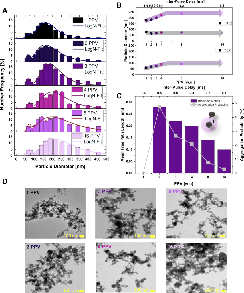
Another hypothesis as to why the B4CC SMSs have substantially smaller particle diameters than anticipated by the model may be due to the interpulse delay (τIP) and the number of PPV, which are both substantially smaller than those in literature-established batch setups [24]. Hence, we systematically varied the PPV from 1 to 16 and, alongside reducing τIP from 1.4 to 0.1 ms at a fluence of 135 mJ·cm−2, monitored differences in the particle size distributions. The fluence of 135 mJ·cm−2 was chosen as it yields the largest particle diameter, while it is still clearly below the fragmentation threshold. The results are shown in Figure 3.
Figure 3:
(A) DLS size distributions for NPs exposed to PPV of 1–16 at 135 mJ·cm−2, with each distribution fitted using a log-normal function to resolve distinct size populations evolving with pulse number. (B) Quantitative evaluation of the bimodal particle size evolution as a function of PPV and interpulse delay that regulates particle fusion dynamics. (C) Calculation of the Brownian motion-driven diffusion lengths of the precursor particles during the interpulse delay linked to PPV, combined with the corresponding Poisson probability of particle collisions enabling fusion events. (D) Representative TEM images across the PPV series.
Figure 3:
(A) DLS size distributions for NPs exposed to PPV of 1–16 at 135 mJ·cm−2, with each distribution fi...
The particle size distribution data from DLS of the PPV studies (Figure 3A) are qualitatively consistent with the TEM observations in Figure 3D and Supporting Information File 1, Figure S9, except for the previously discussed shift in absolute particle diameters. The peak around 50 nm particle size, probably derived from isochoric reshaping, is independent of PPV and τIP. Based on these findings, we can hypothesize that, in this regime, reshaping occurs as a single-pulse event decoupled from particle agglomeration or fusion. Regarding the peaks of the larger particle size fractions, attributed to the pathway of aggregation–melting–fusion, particle size increases with PPV up to a maximum at 4 PPV. This is consistent with previously described mechanisms involving NP heating, melting, and coalescence during laser irradiation by Ishikawa and coworkers [29]. Interestingly, contrary to expectations from the LML’s HME model, beyond 4 PPV, the size increase stagnates, a phenomenon that might be attributed to several hypotheses, which are the mechanistic discoveries of the continuous flat jet LML: (i) Heat: Absorption coefficients of NPs are particle size-dependent and increase with particle diameter. Hence, profound heat accumulation could preferably occur in particles, initiating LFL when a specific particle size threshold is exceeded. However, this is unsupported by our experimental findings as no small fragments were detected by DLS or TEM at the used laser fluence and PPV (see Figure 2E). (ii) Bubbles: With increasing PPV, τIP decreases. Hence, we may have reached a threshold value of τIP where cavitation bubbles generated during melting impair the attachment of educt particles to molten aggregates and limit further particle growth. Consequently, the number of aggregation–melting–fusion steps would be capped. Note that there are indications of gas and bubble formation during LML [61,62], but little is yet known about the size and lifetime of these bubbles [24]. (iii) Sluggish aggregation: There is a minimal PPV threshold for growth initiation, affirmed by the observed stagnant size for more than 4 PPV. It is known that the aggregation rate of colloidal NPs scales with the square of the number concentration [63]. Hence, it is conceivable that additional pulses cannot contribute to further growth when the particle number concentration is too low and, thereby, the aggregation kinetics are too slow. This disables the initiation of subsequent aggregation–melting–fusion steps, resulting in a defined final particle diameter.
While direct kinetic rate constants were not experimentally measured, the observed size plateau beyond 4 PPV (0.4 ms interpulse delay) and the resulting mean particle diameters below the theoretically predicted size maximum strongly indicate a kinetic limitation (kinetic control) rather than a thermodynamic growth limit. To substantiate the sluggish aggregation hypothesis, we calculated the Brownian motion of particles during the pulse repetition interval, which governs the likelihood of particles encountering fusion partners. This was approximated by the Stokes–Einstein equation (D = kBT/(6πηr) at 20 °C, using the viscosity of ethanol and a particle size of 50 nm [64,65] (Figure 3C). A Poisson distribution model shows a sharp decline in aggregation probability beyond 4 PPV with the probability falling to under 5%, which effectively caps particle fusion. These results should only be used to gain an understanding of the behavior and should not be interpreted as absolute numbers. This may explain the plateau in particle size despite increasing pulse numbers (size histograms are displayed in Section S5 of Supporting Information File 1). Thus, both PPV, which imposes a minimum of four pulses before the saturation of particle size occurs due to a concentration limit, and τIP, restricting diffusive repositioning between successive pulses, could evenly contribute to particle growth capping. This dual dependency of the final particle diameter on τIP and the suspension properties, like interparticle distance scaling with concentration, offers further degrees of freedom for upscaling continuous-flow LML. Furthermore, the following interdependencies need to be considered during LML. First, LML mass throughput scales with the concentration, accelerating aggregation and increasing the fusion probability required to form the larger SMSs, indicating a size–concentration correlation. Second, laser systems with even higher repetition rates would be difficult to implement as they must be matched by higher flow speeds to reach higher (i.e., above 4) PPV values, in turn providing lower τIP.
In future studies, this parameter matching could be mechanistically elucidated by altering τIP at a constant PPV by changing the residence time in the LML zone (e.g., by doubling flow speed and repetition rate). Also, testing different feedstock particle concentrations would be straightforward, at least up to a threshold where the fluence drop along the beam path through the jet thickness is insignificant. Another playground for tuning the aggregation rate includes altering the liquid properties, the viscosity, and the Debye length. The Debye length scales with the square root of the medium’s permittivity, and a shorter Debye length would destabilize the suspension, accelerate agglomeration, and potentially improve SMS formation.
But the aggregation-limiting factor can also be considered useful from an application perspective. A major advantage of flat jet SMS synthesis, experimentally evidenced in this study, is that the product particle size is constant above a certain PPV value, rendering the flow-through LML process robust against flow rate fluctuations. Furthermore, while the thermodynamic optimum is always achieved in the batch process at extended processing time, it can be specifically influenced kinetically in the continuous flow process, making the process even more versatile for isolating intermediates [66]. After having identified the intended “arrest” size, only the number of pulses required to synthesize a specific particle type needs to be “invested”, without wasting energy by unnecessarily applying laser pulses. Furthermore, it should be noted that B4C SMS formation is also possible with highly chemically contaminated particles, omitting the need for expensive, highly pure feedstock particles, although the impact of the impurities on the mechanical properties of the SMSs needs to be evaluated in future studies.
As a competing mechanism to LML, LFL occurs at a higher fluence in Figure 2E; this is indicated by a distinct cutoff in the expected particle growth at a laser fluence exceeding 150 mJ·cm−2. For particles around 100 nm, as observed in Figure 2C, this fluence provides sufficient energy to exceed the threshold fluence for LFL. Consequently, the process yields reshaped spheres of approximately 50 nm, representing one facet of the thermodynamic optimum, while particles exceeding ≈100 nm may undergo fragmentation via mechanisms such as phase explosion upon subsequent pulses, producing ultrasmall B4CC NPs (≈2 nm; Supporting Information File 1, Figure S7 and Section S3) [46,67,68]. These ultrasmall particles correspond to recent findings by Ziefuß et al. [38] using identical wavelength and pulse duration (but higher fluences). This contrasts with reports by Koshizaki et al. on nanosecond-pulsed laser-induced LML of boron [24] and boron carbide [26,69,70]. The apparent discrepancies between the two experimental observations can be rationalized by fluence gradients inherent to the respective setups. These gradients arise from spatial intensity distributions within individual laser pulses, the optical penetration depth of the laser in colloidal suspensions, and from partial shielding by larger particles. While Figure 2C assumes a uniform fluence distribution, both spatial and temporal inhomogeneities of the laser field are unavoidable. In flat liquid jet configurations, optical path and irradiated volume are well defined, resulting in a narrow fluence window and a sharply resolved transition between LML and LFL. By contrast, batch reactors exhibit a pronounced fluence drop across the optical path due to absorption and scattering, which superimposes both processes and obscures this transition. Moreover, previous studies primarily analyzed the sediment fraction, which predominantly contains larger and more compact particles, while smaller NPs were not systematically evaluated.
Conclusion
The controlled synthesis of hard-ceramic nanoparticles (NPs) and sub-micrometer spheres (SMSs) remains a key challenge in materials science as it requires precise control over particle size, crystallinity, and sphericity to tailor functional performance. Achieving this balance demands a mechanistic understanding of how aggregation, melting, and fusion kinetics jointly determine size selectivity and yield. Laser melting in liquids (LML) provides a direct and chemically clean route to reorganize NPs through spatially and temporally confined energy input. In accordance with the principles of green chemistry, LML enables solvent-based, reagent-free synthesis, offering a sustainable platform for the controlled fabrication of SMSs. However, scalability limitations inherent to conventional batch-mode LML hinder its translation to industrial production. Bridging this gap requires the development of a continuous LML technique that preserves precise control over the interaction between laser and matter. This study implements the LML concept in a flat jet reactor, enabling a systematic and decoupled evaluation of the effects of laser parameters on SMSs formation. Boron carbide was chosen as the model material not only because of its high application relevance, but also due to its high melting point (difficult to process by other methods) and chemical inertness (robust in LML), making it an ideal benchmark for extending LML towards continuous operation.
Transmission electron microscopy and dynamic light scattering analyses reveal a bimodal product distribution. These two size fractions comprise a fluence-independent population centered at ≈50 nm, attributed to particle reshaping, and an aggregation–fusion-driven fraction spanning 100–225 nm. However, in the flat jet configuration, this growth remains kinetically constrained as the thermodynamically predicted particle sizes of 225–375 nm do not form. Hence, flow-through LML may continuously produce size intermediates that have been inaccessible in prolonged batch reactor LML processing. Furthermore, XRD and XPS characterizations in combination demonstrate the effective elimination of oxide impurities, thus validating the LML synthesis method.
The flat jet experiments further underscore the necessity of incorporating fragmentation fluence thresholds into theoretical models. At fluences exceeding 150 mJ·cm−2, fragmentation of larger spheres in the flat jet system generates ultrasmall NPs, underlining the advantage of flat jet LML in precise fluence control within the excited volume (no beam refraction, minimized beam attenuation along the thin liquid layer). To elucidate the formation dynamics and the apparent deviation from thermodynamic growth, variations in pulse per volume (PPV, up to 16) indicate that fusion-mediated size increase requires at least four pulses. This constraint probably arises from limited Brownian diffusion and low collision rates (≈5%). This goes along with the use of a high‑repetition-rate laser system (required for decent throughput), where the short pulse intervals restrict the number of interparticle collision events and thus growth based on an aggregation–melting–fusion mechanism. These effects yield a persistent 50 nm population and a fluence-dependent secondary modal size fraction exceeding 80 nm with a mass yield of ≈85% at 135 mJ·cm−2. This decouples the LML process from thermodynamic equilibrium conditions and further allows for control of particle size distributions by interpulse delay time and particle mass concentration, yielding particles of ≈100 nm, notoriously difficult to synthesize with laser-based synthesis routes.
Productivity Estimation
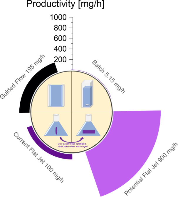
A comparative analysis of the productivity of established synthesis methods for SMSs by LML allows us to classify and rank the scaling potential of the flat jet approach as specified in Figure 4. The calculations supporting these values are provided in Supporting Information File 1, Section S6. An automated, exchangeable batch reactor serves as the baseline for comparison and achieves a productivity of 5.15 mg·h−1[32]. The optimized guided flow reactor achieves 195 mg·h−1[29], underscoring the significant potential of flow-based reactors during scalable synthesis. However, the reactor’s design constraints inherently limit this performance, suggesting that the system has likely reached its maximum productivity. The current flat jet reactor yields 100 mg·h−1. However, by fully exploiting advanced laser parameters, particularly the power (here 400 W) and repetition rate (10 kHz) of high-power nanosecond laser systems, productivity approaching 900 mg·h−1 can be rapidly attained, while future beam shaping strategies may further enhance process control and selectivity [71]. Extrapolating from studies on heating, a fourfold increase in feedstock particle concentration is feasible, enabling substantially enhanced outputs. This significant productivity enhancement establishes the industrial relevance of the flat jet flow reactor, particularly for SMS synthesis. This method enables scalable production with precisely tunable particle characteristics and opens new pathways for materials preparation in research-intensive and application-driven fields. Employing the “unused” laser energy that exits the flat jet would maximize the usage of the available laser power. This could be done, for example, by stacking LML jets or increasing the jet thickness along the trade-off between energy usage (energy-specific LML mass throughput) and fluence deviation-caused SMS size precision loss (decreasing product quality). The flat jet technique’s capacity for rapid throughput and flexible process control positions it as a transformative advancement for both fundamental research and upscaled material production.
Figure 4:
Productivity metrics of common pulsed laser melting in liquid synthesis routes for sub-micrometer spheres, showing production rates scaling with synthesis innovations.
Figure 4:
Productivity metrics of common pulsed laser melting in liquid synthesis routes for sub-micrometer s...
We would like to thank Julian Fink, Tobias Bessel, Florian de Kock, Kirsten Schwark, and Jurij Jakobi for their support. The development of the flat jet system and the characterization of the particles would not have been possible without their dedicated contribution. Artificial intelligence was used as an aid in the linguistic revision of the manuscript. All experimental work and the underlying scientific content were carried out independently by the author and were not influenced by artificial intelligence. A part of this work was conducted at the Laboratory of XPS Analysis, Joint-use Facilities, Hokkaido University.
Funding
We gratefully acknowledge financial support from GF-GG under project no.: 491146928 (DFG-GEPRIS). We also gratefully acknowledge the DFG Deutsche Forschungsgemeinschaft for its financial support under project number 555656461. The XPS part was supported by “Advanced Research Infrastructure for Materials and Nanotechnology in Japan (ARIM)” of the Ministry of Education, Culture, Sports, Science and Technology (MEXT), proposal number JPMXP1226HK0007.
Data Availability Statement
Data generated and analyzed during this study is available from the corresponding author upon reasonable request.
Yan, Z.; Gao, Y.; Zhang, H. Appl. Sci.2023,13, 10957. doi:10.3390/app131910957
Return to citation in text:
[1]
Bafakeeh, O. T.; Shewakh, W. M.; Abu-Oqail, A.; Abd-Elaziem, W.; Abdel Ghafaar, M.; Abu-Okail, M. Polymers (Basel, Switz.)2021,13, 4116. doi:10.3390/polym13234116
Return to citation in text:
[1]
Singhal, V.; Shelly, D.; Saxena, A.; Gupta, R.; Verma, V. K.; Jain, A. Lubricants2025,13, 93. doi:10.3390/lubricants13020093
Return to citation in text:
[1]
Tatami, J.; Kodama, E.; Watanabe, H.; Nakano, H.; Wakihara, T.; Komeya, K.; Meguro, T.; Azushima, A. J. Ceram. Soc. Jpn.2008,116, 749–754. doi:10.2109/jcersj2.116.749
Return to citation in text:
[1]
Okada, M.; Yoshimoto, F.; Watanabe, H.; Nikawa, M. J. Manuf. Processes2023,89, 410–429. doi:10.1016/j.jmapro.2023.01.055
Return to citation in text:
[1]
Yu, Z.; Zheng, Y.; Sun, J.; Zhao, J. Int. J. Refract. Met. Hard Mater.2026,134, 107436. doi:10.1016/j.ijrmhm.2025.107436
Return to citation in text:
[1]
Du, C.; Yu, T.; Sui, X.; Zhang, Z.; Cai, R.; Zhang, L.; Feng, Y.; Feng, M.; Zhou, F.; Wang, D. Adv. Mater. (Weinheim, Ger.)2025,37, 2413781. doi:10.1002/adma.202413781
Return to citation in text:
[1]
Xing, Y.; Deng, J.; Wang, X.; Meng, R. Wear2015,342–343, 1–12. doi:10.1016/j.wear.2015.08.002
Return to citation in text:
[1]
Jendrzej, S.; Gondecki, L.; Debus, J.; Moldenhauer, H.; Tenberge, P.; Barcikowski, S.; Gökce, B. Appl. Surf. Sci.2019,467–468, 811–818. doi:10.1016/j.apsusc.2018.10.060
Return to citation in text:
[1]
Kambale, K. R.; Mahajan, A.; Butee, S. P. Met. Powder Rep.2019,74, 130–136. doi:10.1016/j.mprp.2019.04.060
Return to citation in text:
[1]
Palmero, P. Nanomaterials2015,5, 656–696. doi:10.3390/nano5020656
Return to citation in text:
[1]
Domnich, V.; Reynaud, S.; Haber, R. A.; Chhowalla, M. J. Am. Ceram. Soc.2011,94, 3605–3628. doi:10.1111/j.1551-2916.2011.04865.x
Return to citation in text:
[1]
Mohammad Sharifi, E.; Karimzadeh, F.; Enayati, M. H. Adv. Powder Technol.2011,22, 354–358. doi:10.1016/j.apt.2010.05.002
Return to citation in text:
[1]
Jafari, A.; Mosavat, M.; Meidanchi, A.; Hossienkhani, H. J. Chem. Res.2018,42, 73–76. doi:10.3184/174751918x15178264975471
Return to citation in text:
[1]
Xu, S.; Yu, Y.; Zhang, B.; Zhu, K.; Cheng, Y.; Zhang, T. RSC Adv.2025,15, 10717–10730. doi:10.1039/d5ra00734h
Return to citation in text:
[1]
Chioatto, E.; Mancinelli, S.; Mazzanti, M.; Onofrio, F. Curr. Opin. Green Sustainable Chem.2024,50, 100976. doi:10.1016/j.cogsc.2024.100976
Return to citation in text:
[1]
Venkatesan, K.; Sundarababu, J.; Anandan, S. S. Green Chem. Lett. Rev.2024,17, 2312848. doi:10.1080/17518253.2024.2312848
Return to citation in text:
[1]
Ishikawa, Y.; Tsuji, T.; Sakaki, S.; Koshizaki, N. Prog. Mater. Sci.2023,131, 101004. doi:10.1016/j.pmatsci.2022.101004
Return to citation in text:
[1]
[2]
[3]
[4]
[5]
[6]
Ziefuß, A. R.; Tibbetts, K. M.; Barcikowski, S., Eds. Handbook of Green Laser Synthesis & Processing of Colloids, 3rd ed.; University of Duisburg-Essen: Duisburg Essen, Germany, 2025. doi:10.17185/duepublico/84588
Return to citation in text:
[1]
Ishikawa, Y.; Shimizu, Y.; Sasaki, T.; Koshizaki, N. Appl. Phys. Lett.2007,91, 161110. doi:10.1063/1.2799786
Return to citation in text:
[1]
[2]
Suehara, K.; Takai, R.; Ishikawa, Y.; Koshizaki, N.; Omura, K.; Nagata, H.; Yamauchi, Y. ChemPhysChem2021,22, 675–683. doi:10.1002/cphc.202001000
Return to citation in text:
[1]
[2]
Ishikawa, Y.; Sasaki, T.; Koshizaki, N. J. Nanosci. Nanotechnol.2010,10, 5467–5470. doi:10.1166/jnn.2010.1947
Return to citation in text:
[1]
[2]
Nakamura, D.; Koshizaki, N.; Shishido, N.; Kamiya, S.; Ishikawa, Y. Nanomaterials2021,11, 2201. doi:10.3390/nano11092201
Return to citation in text:
[1]
Koshizaki, N.; Ishikawa, Y. Formation Mechanism of Spherical Submicrometer Particles by Pulsed Laser Melting in Liquid. In High-Energy Chemistry and Processing in Liquids; Ishikawa, Y.; Nakamura, T.; Saeki, M.; Sato, T.; Sugiyama, T.; Wada, H.; Yatsuhashi, T., Eds.; Springer Nature: Singapore, 2022; pp 115–135. doi:10.1007/978-981-16-7798-4_7
Return to citation in text:
[1]
Takai, R.; Koshizaki, N.; Ishikawa, Y.; Hakuta, Y. Chem. Eng. Sci.2020,219, 115580. doi:10.1016/j.ces.2020.115580
Return to citation in text:
[1]
[2]
Friedenauer, T.; Buck, K.; Eberwein, M.; Bünte, A.-L.; Rehbock, C.; Barcikowski, S. Part. Part. Syst. Charact.2023,40, 2300034. doi:10.1002/ppsc.202300034
Return to citation in text:
[1]
Tack, M.; Usama, M.; Kazamer, N.; Exner, K. S.; Brodmann, M.; Barcikowski, S.; Reichenberger, S. ACS Appl. Energy Mater.2024,7, 4057–4067. doi:10.1021/acsaem.4c00342
Return to citation in text:
[1]
[2]
Friedenauer, T.; Spellauge, M.; Sommereyns, A.; Rehbock, C.; Huber, H. P.; Barcikowski, S. J. Phys. Chem. C2025,129, 6803–6816. doi:10.1021/acs.jpcc.4c08643
Return to citation in text:
[1]
Zerebecki, S.; Reichenberger, S.; Barcikowski, S. J. Phys. Chem. A2020,124, 11125–11132. doi:10.1021/acs.jpca.0c08787
Return to citation in text:
[1]
[2]
Koch, N. G.; Poschmann, M.; Heumann, S.; Puthussery, A. J.; Čolić, V.; Barcikowski, S.; Reichenberger, S. ChemCatChem2025,17, e00622. doi:10.1002/cctc.202500622
Return to citation in text:
[1]
[2]
Ziefuß, A. R.; Stratmann, N.; Reifenrath, C.; Kanu, G.; Berndt, N.; Disch, S.; Barcikowski, S. Opt. Lett.2026,51, 437–440. doi:10.1364/ol.582519
Return to citation in text:
[1]
[2]
Saeki, M.; Taguchi, T.; Nakashima, N.; Ohba, H. J. Photochem. Photobiol., A2015,299, 189–193. doi:10.1016/j.jphotochem.2014.11.022
Return to citation in text:
[1]
Sakaki, S.; Ikenoue, H.; Tsuji, T.; Ishikawa, Y.; Koshizaki, N. Appl. Surf. Sci.2018,435, 529–534. doi:10.1016/j.apsusc.2017.10.235
Return to citation in text:
[1]
[2]
[3]
Khairani, I. Y.; Mínguez-Vega, G.; Doñate-Buendía, C.; Gökce, B. Phys. Chem. Chem. Phys.2023,25, 19380–19408. doi:10.1039/d3cp01214j
Return to citation in text:
[1]
Ishikawa, Y.; Katou, Y.; Koshizaki, N.; Feng, Q. Chem. Lett.2013,42, 530–531. doi:10.1246/cl.130044
Return to citation in text:
[1]
Huang, H.; Zhigilei, L. V. Sci. China: Phys., Mech. Astron.2022,65, 274206. doi:10.1007/s11433-021-1881-8
Return to citation in text:
[1]
Huang, H.; Zhigilei, L. V. J. Phys. Chem. C2021,125, 13413–13432. doi:10.1021/acs.jpcc.1c03146
Return to citation in text:
[1]
[2]
Plech, A.; Tack, M.; Huang, H.; Arefev, M.; Ziefuß, A. R.; Levantino, M.; Karadas, H.; Chen, C.; Zhigilei, L. V.; Reichenberger, S. ACS Nano2024,18, 10527–10541. doi:10.1021/acsnano.3c12314
Return to citation in text:
[1]
[2]
Sheindlin, M.; Vervikishko, P.; Bgasheva, T.; Bulava, A.; Frolov, A.; Vasin, A. Phys. Rev. B2025,111, 214105. doi:10.1103/physrevb.111.214105
Return to citation in text:
[1]
Pyatenko, A.; Wang, H.; Koshizaki, N.; Tsuji, T. Laser Photonics Rev.2013,7, 596–604. doi:10.1002/lpor.201300013
Return to citation in text:
[1]
[2]
Sakaki, S.; Ikenoue, H.; Tsuji, T.; Ishikawa, Y.; Koshizaki, N. ChemPhysChem2017,18, 1101–1107. doi:10.1002/cphc.201601175
Return to citation in text:
[1]
[2]
[3]
[4]
Arefev, M. I.; Valavanis, A. S.; Zhigilei, L. V. J. Phys. Chem. C2026,130, 1042–1066. doi:10.1021/acs.jpcc.5c06989
Return to citation in text:
[1]
Paltauf, G.; Dyer, P. E. Chem. Rev.2003,103, 487–518. doi:10.1021/cr010436c
Return to citation in text:
[1]
Spellauge, M.; Tack, M.; Streubel, R.; Miertz, M.; Exner, K. S.; Reichenberger, S.; Barcikowski, S.; Huber, H. P.; Ziefuß, A. R. Small2023,19, 2206485. doi:10.1002/smll.202206485
Return to citation in text:
[1]
Larruquert, J. I.; Pérez-Marín, A. P.; García-Cortés, S.; Rodríguez-de Marcos, L.; Aznárez, J. A.; Méndez, J. A. J. Opt. Soc. Am. A2012,29, 117. doi:10.1364/josaa.29.000117
Return to citation in text:
[1]
Arita, Y.; Nishi, Y.; Amaya, M.; Matsui, T. Thermochim. Acta2000,352–353, 39–42. doi:10.1016/s0040-6031(99)00434-7
Return to citation in text:
[1]
Letzel, A.; Gökce, B.; Menzel, A.; Plech, A.; Barcikowski, S. Appl. Surf. Sci.2018,435, 743–751. doi:10.1016/j.apsusc.2017.11.130
Return to citation in text:
[1]
Li, S.; Marshall, J. S.; Liu, G.; Yao, Q. Prog. Energy Combust. Sci.2011,37, 633–668. doi:10.1016/j.pecs.2011.02.001
Return to citation in text:
[1]
Lin, C.-H.; Zhu, C. Chapter 3 - Relevance of Particle Transport in Surface Deposition and Cleaning. In Developments in Surface Contamination and Cleaning, 2nd ed.; Kohli, R.; Mittal, K. L., Eds.; William Andrew Publishing, 2008; Vol. 1, pp 91–118. doi:10.1016/b978-0-323-29960-2.00003-4
Return to citation in text:
[1]
Tsuji, T.; Takade, I.; Tsuji, M.; Ishimawa, Y.; Koshizaki, N. J. Laser Micro/Nanoeng.2015,10, 329–333. doi:10.2961/jlmn.2015.03.0017
Return to citation in text:
[1]
Tabayashi, Y.; Sakaki, S.; Koshizaki, N.; Yamauchi, Y.; Ishikawa, Y. Langmuir2021,37, 7167–7175. doi:10.1021/acs.langmuir.1c00736
Return to citation in text:
[1]
Pustovalov, V. K. Appl. Phys. A: Mater. Sci. Process.2020,126, 196. doi:10.1007/s00339-020-3370-6
Return to citation in text:
[1]
Bukosky, S. C.; Dev, S.; Allen, M. S.; Allen, J. W. Beilstein J. Nanotechnol.2021,12, 413–423. doi:10.3762/bjnano.12.33
Return to citation in text:
[1]
Zhou, Y.; Huang, M.; Tian, F.; Shi, X.; Zhang, X. J. Chem. Phys.2024,160, 054109. doi:10.1063/5.0189490
Return to citation in text:
[1]
Zhong, H.; Lin, Z. Opt. Express2025,33, 30073–30087. doi:10.1364/oe.567763
Return to citation in text:
[1]
Lau, M.; Ziefuß, A.; Komossa, T.; Barcikowski, S. Phys. Chem. Chem. Phys.2015,17, 29311–29318. doi:10.1039/c5cp04296h
Return to citation in text:
[1]
Pustovalov, V. K. Nanotechnol. Precis. Eng.2024,8, 025001. doi:10.1063/10.0034539
Return to citation in text:
[1]
Havelka, O.; Cvek, M.; Urbánek, M.; Łukowiec, D.; Jašíková, D.; Kotek, M.; Černík, M.; Amendola, V.; Torres-Mendieta, R. Nanomaterials2021,11, 1538. doi:10.3390/nano11061538
Return to citation in text:
[1]
Kondo, M.; Shishido, N.; Kamiya, S.; Kubo, A.; Umeno, Y.; Ishikawa, Y.; Koshizaki, N. Part. Part. Syst. Charact.2018,35, 1800061. doi:10.1002/ppsc.201800061
Return to citation in text:
[1]
Ishikawa, Y.; Feng, Q.; Koshizaki, N. Appl. Phys. A: Mater. Sci. Process.2010,99, 797–803. doi:10.1007/s00339-010-5745-6
Return to citation in text:
[1]
Molina-Prados, S.; Bulgakova, N. M.; Bulgakov, A. V.; Lancis, J.; Mínguez-Vega, G.; Doñate-Buendía, C. Beilstein J. Nanotechnol.2026,17, 309–342. doi:10.3762/bjnano.17.22
Return to citation in text:
[1]
Plech, A.; Tack, M.; Huang, H.; Arefev, M.; Ziefuß, A. R.; Levantino, M.; Karadas, H.; Chen, C.; Zhigilei, L. V.; Reichenberger, S. ACS Nano2024,18, 10527–10541. doi:10.1021/acsnano.3c12314
Lin, C.-H.; Zhu, C. Chapter 3 - Relevance of Particle Transport in Surface Deposition and Cleaning. In Developments in Surface Contamination and Cleaning, 2nd ed.; Kohli, R.; Mittal, K. L., Eds.; William Andrew Publishing, 2008; Vol. 1, pp 91–118. doi:10.1016/b978-0-323-29960-2.00003-4
Spellauge, M.; Tack, M.; Streubel, R.; Miertz, M.; Exner, K. S.; Reichenberger, S.; Barcikowski, S.; Huber, H. P.; Ziefuß, A. R. Small2023,19, 2206485. doi:10.1002/smll.202206485
Larruquert, J. I.; Pérez-Marín, A. P.; García-Cortés, S.; Rodríguez-de Marcos, L.; Aznárez, J. A.; Méndez, J. A. J. Opt. Soc. Am. A2012,29, 117. doi:10.1364/josaa.29.000117
Plech, A.; Tack, M.; Huang, H.; Arefev, M.; Ziefuß, A. R.; Levantino, M.; Karadas, H.; Chen, C.; Zhigilei, L. V.; Reichenberger, S. ACS Nano2024,18, 10527–10541. doi:10.1021/acsnano.3c12314
Havelka, O.; Cvek, M.; Urbánek, M.; Łukowiec, D.; Jašíková, D.; Kotek, M.; Černík, M.; Amendola, V.; Torres-Mendieta, R. Nanomaterials2021,11, 1538. doi:10.3390/nano11061538
Bafakeeh, O. T.; Shewakh, W. M.; Abu-Oqail, A.; Abd-Elaziem, W.; Abdel Ghafaar, M.; Abu-Okail, M. Polymers (Basel, Switz.)2021,13, 4116. doi:10.3390/polym13234116
4.
Singhal, V.; Shelly, D.; Saxena, A.; Gupta, R.; Verma, V. K.; Jain, A. Lubricants2025,13, 93. doi:10.3390/lubricants13020093
Ziefuß, A. R.; Tibbetts, K. M.; Barcikowski, S., Eds. Handbook of Green Laser Synthesis & Processing of Colloids, 3rd ed.; University of Duisburg-Essen: Duisburg Essen, Germany, 2025. doi:10.17185/duepublico/84588
Molina-Prados, S.; Bulgakova, N. M.; Bulgakov, A. V.; Lancis, J.; Mínguez-Vega, G.; Doñate-Buendía, C. Beilstein J. Nanotechnol.2026,17, 309–342. doi:10.3762/bjnano.17.22
Zerebecki, S.; Reichenberger, S.; Barcikowski, S. J. Phys. Chem. A2020,124, 11125–11132. doi:10.1021/acs.jpca.0c08787
37.
Koch, N. G.; Poschmann, M.; Heumann, S.; Puthussery, A. J.; Čolić, V.; Barcikowski, S.; Reichenberger, S. ChemCatChem2025,17, e00622. doi:10.1002/cctc.202500622
Tack, M.; Usama, M.; Kazamer, N.; Exner, K. S.; Brodmann, M.; Barcikowski, S.; Reichenberger, S. ACS Appl. Energy Mater.2024,7, 4057–4067. doi:10.1021/acsaem.4c00342
37.
Koch, N. G.; Poschmann, M.; Heumann, S.; Puthussery, A. J.; Čolić, V.; Barcikowski, S.; Reichenberger, S. ChemCatChem2025,17, e00622. doi:10.1002/cctc.202500622
38.
Ziefuß, A. R.; Stratmann, N.; Reifenrath, C.; Kanu, G.; Berndt, N.; Disch, S.; Barcikowski, S. Opt. Lett.2026,51, 437–440. doi:10.1364/ol.582519
Friedenauer, T.; Buck, K.; Eberwein, M.; Bünte, A.-L.; Rehbock, C.; Barcikowski, S. Part. Part. Syst. Charact.2023,40, 2300034. doi:10.1002/ppsc.202300034
34.
Tack, M.; Usama, M.; Kazamer, N.; Exner, K. S.; Brodmann, M.; Barcikowski, S.; Reichenberger, S. ACS Appl. Energy Mater.2024,7, 4057–4067. doi:10.1021/acsaem.4c00342
35.
Friedenauer, T.; Spellauge, M.; Sommereyns, A.; Rehbock, C.; Huber, H. P.; Barcikowski, S. J. Phys. Chem. C2025,129, 6803–6816. doi:10.1021/acs.jpcc.4c08643