Chair of Materials Science and Additive Manufacturing, School of Mechanical Engineering and Safety Engineering, University of Wuppertal, 42119 Wuppertal, Germany
Chair of Materials Science and Additive Manufacturing, School of Mechanical Engineering and Safety Engineering, University of Wuppertal, 42119 Wuppertal, Germany
Chair of Materials Science and Additive Manufacturing, School of Mechanical Engineering and Safety Engineering, University of Wuppertal, 42119 Wuppertal, Germany
1FZU - Institute of Physics of the Czech Academy of Sciences, Na Slovance 1999/2, 18200 Prague 8, Czech Republic
2Chair of Materials Science and Additive Manufacturing, School of Mechanical Engineering and Safety Engineering, University of Wuppertal, 42119 Wuppertal, Germany
Guest Editor: G. Mínguez-Vega Beilstein J. Nanotechnol.2026,17, 1605–1623.https://doi.org/10.3762/bjnano.17.110 Received 11 Sep 2026,
Accepted 22 Oct 2026,
Published 12 Nov 2026
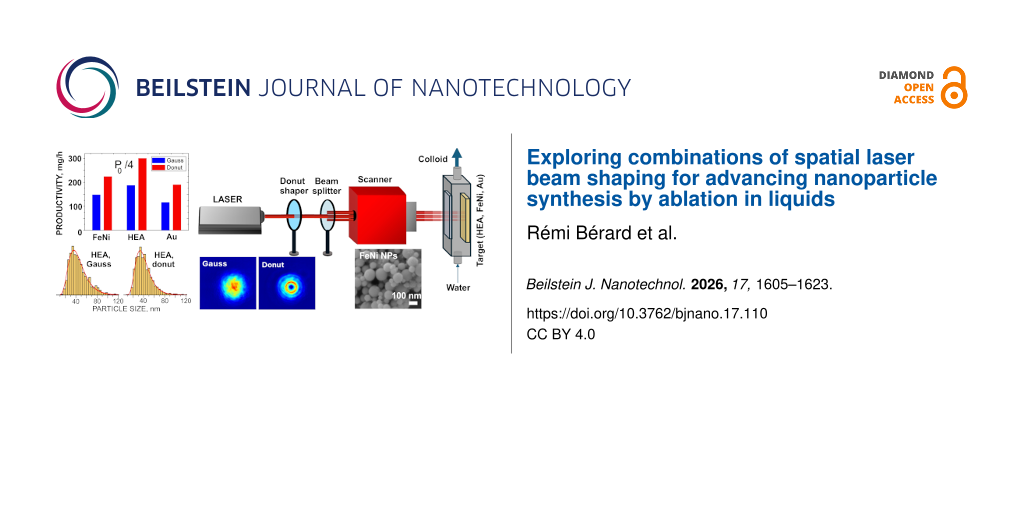
Pulsed laser ablation in liquids (PLAL) is a versatile and sustainable technique for the synthesis of ligand-free colloidal nanoparticles, but its wider application is limited by relatively low productivity and insufficient control over particle size distributions. Here, to advance the technique, we investigate the possibility of combining in one synthesis process the advantages of two recently developed cost-effective approaches, multibeam PLAL for productivity increase and donut-shaped laser beams for particle size modification. Nanoparticles of gold, an iron–nickel alloy, and a high-entropy alloy were produced in water using single-beam and multibeam configurations with four and eleven picosecond sub-beams. The effects of beam profile, beam-splitting factor, and laser fluence on particle yield and size distributions were systematically evaluated. Splitting donut-shaped beams is shown to offer a similar productivity increase as Gaussian pulses, and, at moderate fluences, multiple donut beams can be even more efficient. A single donut-shaped beam generally reduces the particle size, but, in a multibeam configuration, the reduction effect is hindered by secondary processes such as the interaction of cavitation bubbles, nanoparticle fragmentation, and redeposition. The results demonstrate the feasibility of combining donut-shaped beams with multibeam ablation in PLAL synthesis and identify key process parameters that have to be optimized to achieve both high productivity and improved particle size control.
Pulsed laser ablation in liquids (PLAL) has emerged as a versatile and inherently green route for nanoparticle (NP) synthesis [1-4]. Owing to its one-step nature, the absence of added chemical reagents, its applicability to a broad range of solid materials, and the direct production of colloidal NPs suitable for subsequent processing, PLAL provides a convenient alternative to conventional wet-chemistry routes for applications in medicine [5-7], catalysis [8,9], sensing [10,11], and additive manufacturing [12,13]. In the broader context of resource scarcity and environmental constraints [14,15], the low material consumption and surfactant-free character of PLAL are particularly attractive.
Despite these advantages, two major limitations still hinder the widespread industrial application of PLAL-produced NPs, namely, relatively low production rates and insufficient control over NP size distributions [16]. The first limitation is caused mainly by the cavitation bubble generated during PLAL, which shields the subsequent laser pulses thus reducing the ablation rate and hence the NP synthesis productivity [2,17,18]. Other shielding effects, including those caused by persistent microbubbles [19] and suspended nanoparticles [2,20], as well as redeposition processes [21], and nonlinear absorption [2,22] can also reduce ablation efficiency in liquids. The second challenge, namely, obtaining narrow, unimodal NP size distributions, is associated with several mechanisms involved in NP formation, growth, and fragmentation during PLAL. The interplay among these mechanisms often results in several NP populations and, consequently, broad or bimodal size distributions [2,23-26].
Considerable efforts have been made to overcome these two limitations of the PLAL technique. Various strategies have been employed to increase the ablation efficiency in liquid environments and thus enhance the NP yield, including optimization of irradiation conditions [27-30] and target geometry [31-33], the use of liquid-flow reactors [34,35] and spatiotemporal focusing [22]. A milestone in upscaling PLAL synthesis was achieved by Streubel et al. [17], who demonstrated the industrial-scale level of NP synthesis productivity by using a combination of a high-repetition-rate laser, liquid flow, and rapid, supersonic scanning of the laser beam over the target, thus bypassing the cavitation bubble. However, the fast polygon scanner employed in this approach is an expensive and technically complex component, which may limit its widespread practical use. More recently, a multibeam (MB) PLAL technique was developed [18,36,37] that allows the cavitation-bubble shielding effect to be mitigated both temporally and spatially through the use of inexpensive diffractive optical elements (DOEs). The MB-PLAL method has demonstrated NP synthesis productivity comparable to that achieved using polygon scanners, while providing a potentially more reliable and cost-effective approach.
Extensive research has been conducted to achieve control over size distributions of PLAL-produced NPs and reduce their width. Several strategies have been developed including tuning the PLAL processing parameters [2,38-40], quenching of NP growth by adding surfactants [41,42], ligands [43], and low-salinity ions [44], as well as varying liquid media [45] and using two-step laser synthesis involving ablation and fragmentation [46,47]. However, most of the developed NP size-tailoring techniques are not universal and are effective only for specific materials. Moreover, the addition of stabilizers compromises one of the principal advantages of PLAL, namely, its ability to produce surfactant- and ligand-free NPs, and may therefore limit the versatility and applicability of the resulting colloids. Furthermore, one optimized tailoring parameter often affects the others. For instance, narrowing the NP size distribution by reducing laser fluence leads to a drawback of lower productivity [2]. Recently, a new optical approach was developed to modify the size distributions of PLAL-produced NPs by using donut-shaped (DS) laser beams instead of conventional Gaussian beams [37,48]. Experiments with various material classes, including metals, alloys, and oxides, demonstrated that PLAL with DS beams can significantly reduce particle size, narrow the size distribution, and improve particle sphericity.
In this study, building on these recent developments, we investigated the simultaneous implementation of MB-PLAL and picosecond DS laser pulses to combine high productivity and enhanced NP size control within a single PLAL configuration. Colloidal NPs of three materials, gold (Au), an iron–nickel (FeNi) alloy, and a high-entropy alloy (HEA), were produced in water using this approach. The selected materials exhibit substantially different thermophysical properties, particularly different laser-ablation thresholds, while their NPs are also relevant to a wide range of applications. The resulting colloids were characterized in terms of NP synthesis productivity and particle size distribution. Their characteristics were compared with those of NPs produced from the same materials using single-beam PLAL with Gaussian laser pulses.
Experimental
Pulsed laser ablation in water
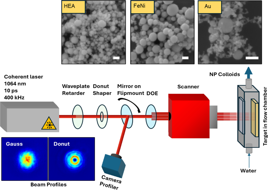
The PLAL setup is schematically shown in Figure 1. The target is positioned in a vertical flow-through aluminium chamber (internal dimensions are 85 × 30 × 10 mm3) using double-sided adhesive tape. The tested targets were polycrystalline Fe0.5Ni0.5 alloy (1 × 20 × 70 mm3, 99.95%, Sindlhauser Materials GmbH, Germany), high-entropy Cantor alloy Co0.2Cr0.2Fe0.2Mn0.2Ni0.2 (1 × 20 × 70 mm3, 99.5%, Sindlhauser Materials GmbH), and Au (1 × 20 × 70 mm3, 99.99%, EVOCHEM Advanced Materials GmbH, Germany). The flow rate of demineralized water (Synergy Water Purification System) was adjusted to 300 mL/min using a peristaltic pump that ensured complete filling of the chamber volume under laminar flow conditions (the Reynolds number is ≈140).
Figure 1:
Schematic presentation of the PLAL setup. A donut shaper and a DOE (1×4 or 1×11) can be placed or removed from the beam path to provide different combinations of the beam shaping. The beam profiles (bottom left) are acquired prior to the experiments by flipping a mirror to redirect the beam toward a camera. The inset at the top shows typical SEM images of NPs of the three materials obtained with the donut shaper and the 1×11 DOE (scale bar is 100 nm).
Figure 1:
Schematic presentation of the PLAL setup. A donut shaper and a DOE (1×4 or 1×11) can be placed or r...
The targets were irradiated at normal incidence through the chamber glass window by a Nd:YAG laser (HyperRapid NXT, Coherent Corp., pulse duration 10 ps, wavelength 1064 nm, maximum power 120 W) at a repetition rate of 400 kHz. The output beam had a diameter of 5 mm and a Gaussian intensity profile. A galvo scanner SUPERSCAN IV-15 (Raylase GmbH, Germany) equipped with an f-theta lens (focal distance 167 mm) was used to focus and scan the beam at the target surface with a scanning speed of 20 m/s. The scanning patterns depended on the irradiation conditions as specified in Table 1. The beam power in front of the flow chamber was varied in the range of 3–82 W using a laser attenuator and monitored by a power meter Puls2 (LaserPoint, Vimodrone, Italy). In all experiments, the target was located at the focal plane, unless specified otherwise, and irradiated for 5 min to obtain ≈1.5 L of colloid for every PLAL regime.
Table 1:
Irradiation conditions. For multibeam configurations, pulse energy and fluence correspond to individual sub-beams.
Power notation
Total power, W
Pulse energy, µJ
Fluence, J/cm2
Scanning pattern
Gauss
Donut
single beam
P0
81.2
203
12.6a
5.0a
spiral
P0/2.7
32.6
81.5
9.0
—
P0/4
21.8
54.5
6.0
2.2
P0/11 or P0/4/2.7
8.9
22.3
2.5
0.90
P0/11/2.7
3.4
8.5
0.9
—
DOE 1×4
P0
81.2
50.8
5.6
2.1
raster
P0/2.7
32.6
20.4
2.2
—
DOE 1×11
P0
81.2
18.5
2.0
0.75
spiral
P0/2.7
32.6
7.4
0.82
—
aThe target was shifted 2 mm out of focus to avoid damage of the chamber window.
Three types of spatial shaping of the laser beam were investigated. First, a radially polarized DS beam was produced from the original Gaussian beam using a half-waveplate in combination with a S-waveplate convertor (Workshop of Photonics, Vilnius, Lithuania). The resulting beam shape was controlled using a beam profiler CMOS-1.001-Nano-UV (CINOGY Technologies, Duderstadt, Germany). As the polarization of DS pulses was found to barely affect the PLAL-produced NPs [47], azimuthal polarization was not investigated here. Second, the output beam was split into n sub-beams using static DOEs for multibeam PLAL. Two different DOEs were placed after the galvo scanner to obtain at the target either a horizontal line of four spots separated by 0.7 mm (1×4 DOE, 0.28° beam separation angle, HOLO/OR, Ness Ziona, Israel) or a vertical line of eleven spots separated by 4 mm (1×11 DOE, 1.2° beam separation angle, LIMO Lissotschenko Mikrooptik GmbH, Dortmund, Germany). The DOEs were installed after the lens of the scanner in order to accommodate the use of a large scanning pattern with the 1×11 DOE. Finally, the DOEs were combined with the DS convertor to investigate PLAL with multiple DS beams. The NPs produced with the shaped laser pulses were compared with those obtained in the standard PLAL regime with a single Gaussian beam at different laser fluences.
The combination of the different shaping elements leads to a large variety of experimental conditions with different sub-beam energies and fluences. The investigated ablation regimes are summarized in Table 1. The selected set of conditions enables comparison of different regimes at nearly identical energy and/or fluence in an individual sub-beam, that is, at comparable PLAL conditions, in the fluence range of 0.7–13 J/cm2. The peak fluences for Gaussian beams were evaluated using an effective spot diameter of 48 µm (focal plane, 1/e2 criterion) measured for this setup previously [18]. For donut-shaped beams at the same pulse energy and focusing conditions as for Gaussian beams, the fluence is lower by a factor of ≈2.7 [48,49]. Therefore, to obtain identical fluences in individual sub-beams, the pulse energy of a single Gaussian beam was reduced by a factor of n = 4 or 11 when comparing with multibeam PLAL or by a factor of 2.7 when comparing with donut-shaped beams. Note that the beam splitting with a DOE does not change the shape of the original beam [18]. Note also, that, due to different splitting angles and beam-array dimensions of the used DOEs, different beam scanning patterns were used. For a single beam and 11 sub-beams, this was a hollow spiral with outer and inner diameters of 10 and 4 mm, respectively [50], while for the 1×4 DOE, this was a raster pattern over an area of 6 × 10 mm2[18]. The irradiated area per sub-beam was nearly identical for both DOEs, approximately 60 mm2. With the 1×4 DOE, all four beams irradiated this area, whereas with the 1×11 DOE, it was exposed to one beam and, owing to the overlap of adjacent spiral patterns, it was additionally irradiated by two neighboring beams. Consequently, the number of laser pulses accumulated per spot was approximately two times lower for the 1×11 DOE. To ensure comparable pulse accumulation, the target was shifted to a fresh area after 1×4 DOE runs twice as frequently as for PLAL runs with the spiral scanning pattern.
Characterization
The productivity of NP synthesis was determined from the target mass loss during PLAL. The targets were dried in an oven, cooled down on a metallic plate, and weighed using an analytical balance (Gram, FS220, resolution 0.1 mg) before and after each PLAL experiment. For NP size characterization, approximately 100 mL of colloid was collected after 2 to 3 min of irradiation. The obtained sample was drop-cast and dried on a piece of a ⟨100⟩ silicon wafer, and the deposited NPs were analyzed using a scanning electron microscope (SEM, TESCAN MIRA3 LMH). For each sample, several images were acquired at different places of the droplet to investigate more than 1000 NPs per sample. Particle sizes were extracted from the SEM images using ImageJ. The resulting particle size datasets were subsequently processed using a dedicated script implemented in OriginPro. The script was used to calculate, directly from the experimental data, the median size ⟨D⟩, the median absolute deviation (MAD), and the robust coefficient of variation, RCV = MAD/⟨D⟩ [51], and to perform lognormal fitting of the size distributions. A two-component lognormal model was used to approximate the bimodal distributions of Au NPs. Details of the statistical analysis and fitting procedure are provided in Supporting Information File 1.
Results and Discussion
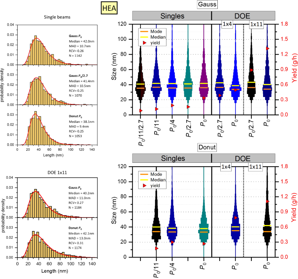
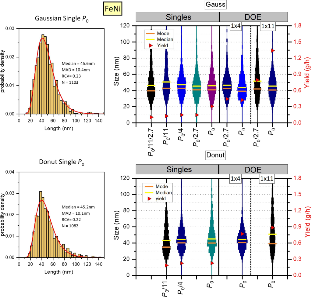
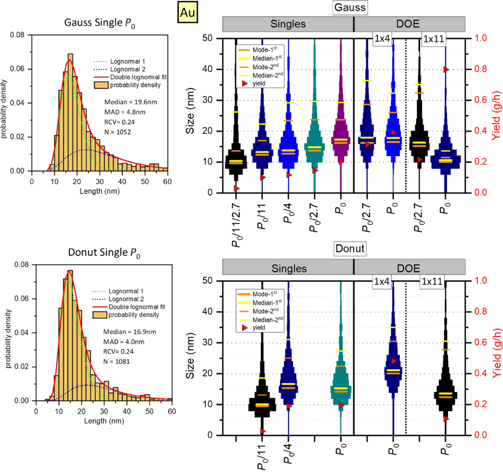
Figures 2, 3, and 4 provide an overview of the productivity and size distributions for PLAL-produced NPs of HEA, FeNi, and gold, respectively. These two key characteristics of the PLAL process are discussed below in the context of various beam-shaping approaches.
Figure 2:
Summary of results for HEA NPs. Left: Examples of size distributions of NPs produced by single Gaussian and DS beams at different powers (top), and by eleven Gaussian and donut-shaped sub-beams at maximal power (bottom). The lines represent lognormal fits. The indicated median size, median absolute deviation (MAD), and robust coefficient of variation (RCV) are derived directly from the particle size data. The number of measured nanoparticles (N) is also indicated. Right: The violin plots showing the NP size distributions for all the samples obtained with Gaussian (top) and donut-shaped (bottom) beams as a function of the total laser power. The plots for an identical fluence have the same color. The mode (orange lines) and median (yellow lines) values are obtained from lognormal fits. The right axis shows the productivity (red triangles).
Figure 2:
Summary of results for HEA NPs. Left: Examples of size distributions of NPs produced by single Gaus...
Figure 3:
Summary of results for FeNi NPs. Left: Examples of size distributions of NPs produced by single Gaussian and DS beams at maximal power. The lines represent lognormal fits. The indicated median size, median absolute deviation (MAD), and robust coefficient of variation (RCV) are derived directly from the particle size data. The number of measured nanoparticles (N) is also indicated. Right: The violin plots showing the NP size distributions for all the samples obtained with Gaussian (top) and donut-shaped (bottom) beams as a function of the total laser power. The plots for an identical fluence have the same color. The mode (orange lines) and median (yellow lines) values are obtained from lognormal fits. The right axis shows the productivity (red triangles).
Figure 3:
Summary of results for FeNi NPs. Left: Examples of size distributions of NPs produced by single Gau...
Figure 4:
Summary of results for Au NPs. Left: Examples of size distributions of NPs produced by single Gaussian and DS beams at maximal power. The NP size distributions are approximated by two lognormal functions for small (green dotted lines) and large (blue dotted lines) NP populations. The indicated median size, median absolute deviation (MAD), and robust coefficient of variation (RCV) are derived directly from the particle size data. The number of measured nanoparticles (N) is also indicated. Right: The violin plots showing the NP size distributions for all the samples obtained with Gaussian (top) and donut-shaped (bottom) beams as a function of the total laser power. The plots for an identical fluence have the same color. The mode (orange lines) and median (yellow lines) values are obtained from lognormal fits and are given for both NP populations. The right axis shows the productivity (red triangles).
Figure 4:
Summary of results for Au NPs. Left: Examples of size distributions of NPs produced by single Gauss...
The obtained productivity values in different PLAL regimes are summarized in Table 2. The accuracy of the obtained values is estimated to be within 5% based on two to three independent measurements for several selected PLAL regimes and our previous similar studies [18]. The uncertainty originates mainly from the fact that the PLAL process is not entirely reproduced under the same irradiation conditions, but not from the errors in the balance measurement (which are virtually negligible).
Table 2:
Productivity of NP synthesis (in mg/h) for different PLAL regimes. The values in parentheses indicate the percentage of the productivity of an individual sub-beam in MB-PLAL compared to the single-beam regime at the same laser fluence.
Power notation
FeNi
HEA
Au
Gauss
Donut
Gauss
Donut
Gauss
Donut
Single beam
P0
307
227
336
269
204
196
P0/2.7
146
—
159
—
146
—
P0/4
148
224
187
300
116
190
P0/11 or P0/4/2.7
127
185
116
176
101
27.6
P0/11/2.7
106
—
84.0
—
28.8
—
DOE 1×4
P0
425 (72%)
769 (86%)
496 (66%)
785 (65%)
391 (84%)
482 (63%)
P0/2.7
445 (88%)
—
386 (83%)
—
316 (78%)
—
DOE 1×11
P0
1341 (96%)
886 (40%)
1318 (103%)
1109 (57%)
799 (72%)
108 (36%)
P0/2.7
796 (68%)
—
889 (96%)
—
216 (68%)
—
Fluence effect for a single Gaussian beam
Laser fluence is one of the most important parameters affecting the PLAL process and determining the NP synthesis productivity [2]. Above a threshold fluence for ablation, the ablation rate, and therefore the productivity, increase gradually until reaching a limitation due to effects such as cavitation-bubble shielding and optical breakdown. In the absence of these limitations (e.g., when the cavitation bubble is effectively bypassed), the ablation rate follows the fluence dependence in air, suggesting that there exists an optimal fluence Fopt with the maximal productivity per average input laser power [2,17]. According to a simple model [52], the optimal fluence of ultrashort laser pulses in air can be estimated as
(1)
where e is the Euler constant and Fth is the ablation threshold.
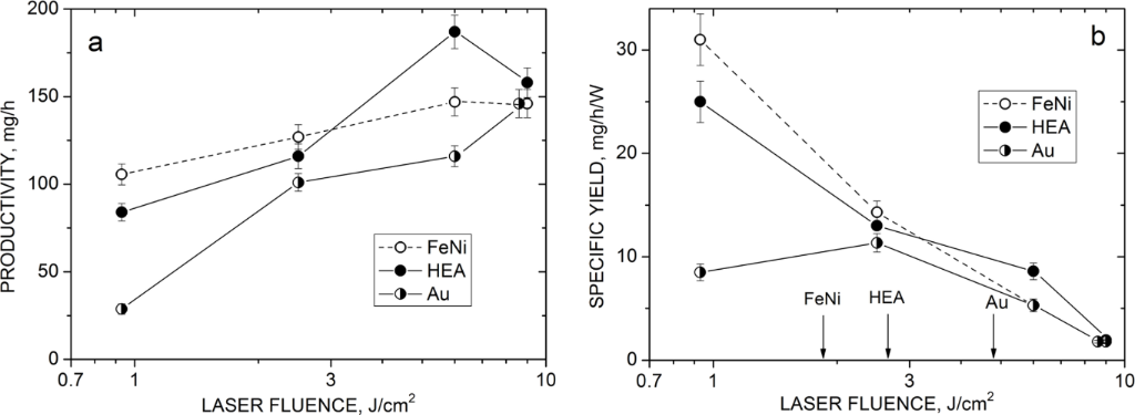
The obtained single-beam productivity values follow the general fluence behavior for Gaussian beams with a gradually increasing dependence for gold and with signs of saturation at fluences above ≈6 J/cm2 for HEA and FeNi (Figure 5a). The data obtained at the highest laser power, P0, were excluded here because they were acquired using a larger irradiation spot and were therefore not directly comparable with the remaining data. Figure 5b shows the productivity data normalized to the average power (i.e., the specific NP yield) as a function of laser fluence. The expected maximum at an optimal fluence is observed only for gold while HEA and FeNi exhibit gradually decreasing fluence dependencies.
Figure 5:
Mass productivity (a) and power-specific productivity (b) of FeNi, HEA, and gold NPs produced by a single Gaussian beam as a function of laser fluence. The arrows in (b) show expected optimal fluences evaluated from Equation 1 (see text for details).
Figure 5:
Mass productivity (a) and power-specific productivity (b) of FeNi, HEA, and gold NPs produced by a ...
The expected optimal fluences for the ideal situation of completely bypassing the cavitation bubble can be estimated using Equation 1. The single-shot ablation thresholds in water for picosecond near-IR laser pulses were reported as 3.36 J/cm2 for gold and 1.3 J/cm2 for FeNi [21]. Under multishot irradiation, as in our case, the threshold fluence is lower due to incubation effects [53-55]. The decrease of the threshold with the number of pulses N was found to follow the equation:
(2)
where Fth(1) is the single-shot threshold and S is an accumulation coefficient whose value for metals and picosecond pulses is typically 0.8 [54], although weaker dependencies were also reported [56]. The average pulse number per spot during our 5 min PLAL experiment can be estimated as N ≈ 3600 assuming uniform irradiation over the scanning patterns. Then, taking S = 0.8, we obtain from Equation 2 the multishot ablation thresholds of 0.65 J/cm2 for gold and 0.24 J/cm2 for FeNi. For the HEA CoCrFeMnNi, the multishot threshold for ablation conditions similar to those in this study was reported as 0.36 J/cm2[50]. The expected optimal fluences, according to Equation 1, are therefore 4.8, 2.66, and 1.85 J/cm2 for Au, HEA, and FeNi, respectively (Figure 5b).
For all three materials, the experimentally observed PLAL conditions corresponding to the maximum specific NP yield are shifted toward lower fluences relative to the values estimated using the air-ablation model (Figure 5b). This indicates that the cavitation bubble is not completely bypassed under the considered conditions, which reduces the NP synthesis productivity in the single-beam regimes. Indeed, although the interpulse distance under our PLAL conditions (50 µm for the 400 kHz pulses scanned at 20 m/s) is almost the same as the spot diameter (48 µm) and thus the nominal spot overlap is negligible, the cavitation bubble grows during the interpulse time (2.5 µs) to larger lateral sizes, above 100 µm, under the considered conditions [18]. Therefore, the bubble shields and reflects the incoming next pulse, reducing the productivity (ablation rate) [2]. The shielding effect is particularly pronounced at high fluences, when the bubble grows faster [18,57]; thus, the optimal irradiation conditions are shifted towards lower fluences, and beyond the optimum, the specific NP yield drops rapidly with fluence (Figure 5b). These limitations for NP synthesis productivity can be overcome by using the multibeam PLAL approach [18,36,37].
Multibeam approach
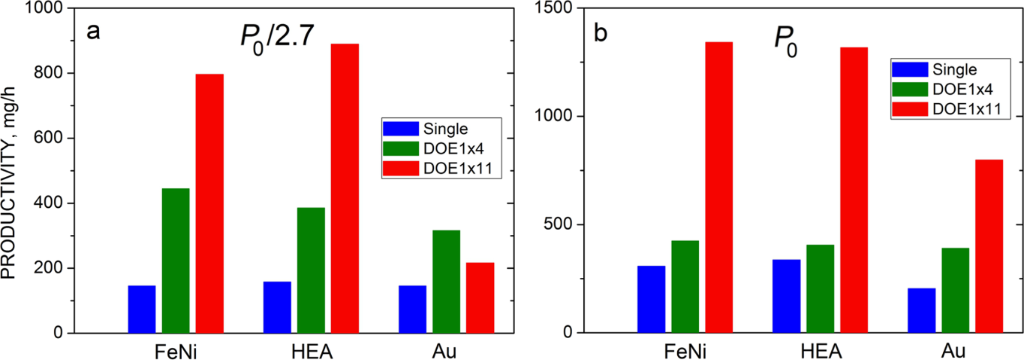
Beam splitting with different splitting factors has recently been demonstrated as an efficient and low-cost method to increase the productivity of the PLAL NP synthesis for Gaussian beams [18,36,37]. The advantage of the approach relies not only on a larger number of laser beams but, more important, on the possibility of bypassing the cavitation bubble [18]. Here we demonstrate the increase in productivity by MB-PLAL of the three studied materials. Figure 6 compares the NP yields for single-beam and MB regimes at identical laser powers of P0/2.7 and P0 (full power) in the case of Gaussian pulses. Note that, at a fixed total power, the laser fluence of an individual sub-beam in the MB-PLAL is lower than that in a single beam by the splitting factor n (Table 1). For all the materials, the MB-PLAL technique offers substantial increases in net productivity. At a P0/2.7 power, the highest benefit from the splitting is for FeNi, a material with the lowest ablation threshold and a weak fluence dependence of the ablation yield (Figure 5a). Thus, a small reduction in the sub-beam productivity with fluence decreased from 9 to 2.2 J/cm2 by the 1×4 DOE is more than compensated by the fourfold increase in the number of beams resulting in the productivity gain by a factor k = 3.0 while those for HEA and Au are 2.5 and 2.2, respectively (Figure 6a). For the 1×11 DOE, the productivity increases by a factor of ≈5.5 for both FeNi and HEA, while only 1.5 times for gold. The small increase in the latter case is likely because of the low fluence in a sub-beam, close to the gold ablation threshold. With the full power, the productivity gain with the 1×4 DOE for all the materials is reduced (k = 1.5, 1.4, and 1.9, for HEA, FeNi, and Au, respectively, Figure 6b), probably due to limitations imposed by the cavitation bubble, which is fairly large and long-lived at this fluence. With the 1×11 DOE, the sub-beam fluence is below 1 J/cm2, the bubble-induced limitations are apparently minor, and the productivity increase factor remains high (≈4) for all three materials.
Figure 6:
Productivity of FeNi, HEA, and Au NPs in single-beam PLAL and MB-PLAL with Gaussian pulses at P0/2.7 (a) and P0 (b) laser powers.
Figure 6:
Productivity of FeNi, HEA, and Au NPs in single-beam PLAL and MB-PLAL with Gaussian pulses at P0/2....
The selected regimes (Table 1) enable us to evaluate potential losses in the productivity of an individual sub-beam in the MB-PLAL relative to a single-beam PLAL at identical fluences. The numbers in parentheses in Table 2 represent the percentage of a split sub-beam productivity compared to the corresponding single-beam PLAL. With the 1×11 DOE, the efficiency of a sub-beam is close to 100% in most cases (except for gold, where sub-beam fluences in these MB regimes are well below optimal values). This is consistent with the large spot separation in this case (4 mm), when significant interaction of simultaneously produced bubbles is unlikely, so there are no productivity losses. The interspot distance is much shorter for the 1×4 DOE (0.7 mm), which may promote bubble interaction [58], thus reducing the sub-beam productivity to ≈85% at P0/2.7 and ≈70% at P0 (Table 2). The bubble interaction can also affect the sizes of the produced NPs [58]; thus, the spot separation is an additional important factor in the MB-PLAL regimes.
We should underline that the possibilities of the splitting technique to bypass the cavitation bubble and to increase the PLAL productivity are not fully exploited in this study. The pulse repetition rate is fixed here in all the regimes, and thus the bypassing effect under MB-PLAL conditions is based merely on a smaller size and shorter lifetime of the bubble induced by a lower-fluence sub-beam. However, the bubble can be temporally bypassed more efficiently by reducing the repetition rate and therewith keeping the sub-beam fluence at a fairly high optimal level at the same total laser power [18,37]. We therefore expect that a considerably higher synthesis efficiency than that obtained here (Figure 5) can be gained in the MB-PLAL by choosing a proper combination of the splitting factor, pulse repetition rate, spot size, and spot separation at a given laser power. Such an optimization is, however, beyond the scope of this work.
Donut-shaped beams
Introducing a donut shaper into the system modifies considerably the irradiation conditions and leads to new factors affecting the PLAL productivity. First, the peak fluence is 2.7 times lower than that with a Gaussian beam at the same pulse energy [37]; this could reduce the ablation rate, in particular at low fluences, near the ablation threshold. Second, the irradiation spot area with a DS pulse is larger and more uniformly heated [48], which can be, in contrast, a favorable factor for the productivity, especially at moderate and high fluences, when the productivity is expected to have only a weak dependence on fluence, similar to Gaussian pulses (Figure 5a). Third, due to a larger spot, the lateral size of the cavitation bubble produced by a DS pulse is also larger, at least at initial stages, which can promote the bubble shielding effect and interaction of neighboring bubbles, thus reducing the productivity, especially at high fluences. Finally, the time evolution of the bubble is more complicated than that induced by a Gaussian pulse with asymmetric expansion and collapse that reduces the bubble lifetime and apparently affects both yield and size of the produced NPs [37,48].
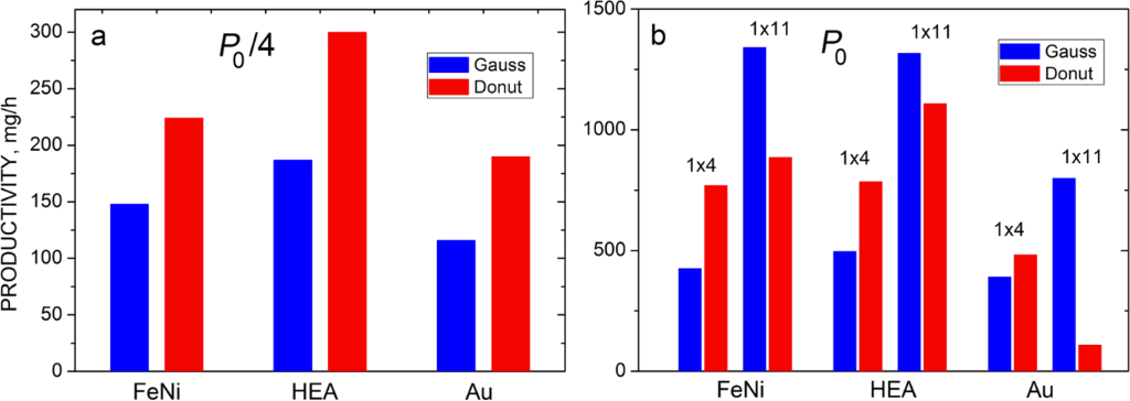
The observed trends are consistent with the above considerations. Indeed, the productivity with a single DS pulse at a moderate fluence of 2.2 J/cm2 (P0/4) is 1.5–1.6 times higher than that with a Gaussian pulse at the same power for all three materials (Figure 7a). This is likely due to a larger and more uniformly irradiated DS laser spot. A similar gain in productivity with the DS pulse is observed at an even lower fluence (0.9 J/cm2, P0/11) for HEA and FeNi, while for Au, the productivity drops dramatically to ≈4 times lower than that of the Gaussian beam (Table 2). The latter is obviously because the sub-beam fluence at P0/11 is too low for gold, near the ablation threshold. The markedly stronger productivity decrease observed for Au compared with FeNi and HEA is likely related to the proximity of the DS-beam fluence to the Au ablation threshold. The DS sub-beam fluence in the P0/11 regime (0.75 J/cm2) exceeds the estimated multishot threshold for Au (0.65 J/cm2) only marginally, whereas it remains approximately two and three times above the corresponding thresholds for HEA and FeNi, respectively. Under such near-threshold conditions, the Au ablation yield becomes particularly sensitive to local fluence variations, shielding effects, and possible redeposition processes, resulting in a substantially stronger productivity degradation.
Figure 7:
Comparison of the NP productivities of Gaussian and donut-shaped pulses in single-beam PLAL at a P0/4 power (a) and in MB-PLAL with the 1×4 and 1×11 DOEs at the full laser power (b).
Figure 7:
Comparison of the NP productivities of Gaussian and donut-shaped pulses in single-beam PLAL at a P0...
When the fluence of the Gaussian beam is reduced to the same value of 0.9 J/cm2 at P0/11/2.7, the productivity is also low and similar to that of the DS pulse at P0/11 (Table 2). On the other hand, when the power increases from P0/4 to P0, the productivity of the DS pulses is not practically changed (and even drops for HEA) while that of the Gaussian pulses still increases (Table 2). This indicates that the bubble-induced shielding is indeed stronger for DS pulses at high fluences.
Note that at near-threshold fluences, DS pulses do not provide an advantage in productivity over Gaussian pulses due to a larger irradiated area, as observed at moderate fluences. This may be associated with a more efficient redeposition of the ablated material back to the target surface in the PLAL process with DS pulses. The redeposition was shown to be responsible for reducing the material removal efficiency in liquids, as compared with air, at low fluences, when the ablated layer does not propagate far from the target and eventually redeposits onto the surface [21]. With DS pulses, the redeposition effect is likely more pronounced since both the propagation distance and lifetime of the ablation plasma plume are shorter than for plasmas induced by Gaussian pulses, as was demonstrated in plasma imaging experiments [59]. The observed productivity decrease with near-threshold DS pulses can therefore be due to a combination of two factors. First, the lower fluence of DS pulses makes the process more sensitive to threshold-related reductions in ablation efficiency. Second, shorter propagation distances and lifetimes of the ablation plasma may promote redeposition of ablated material onto the target surface. The present experiments do not allow these contributions to be separated quantitatively; thus, enhanced redeposition should be regarded as a plausible contributing mechanism rather than a directly verified explanation.
A comparison of the productivities of Gaussian and DS pulses in the MB-PLAL regimes shows similar tendencies as for single beams (Figure 7b). With the splitting factor n = 4 at the full power, when the sub-beam fluence is kept at a moderate value of 2.1 J/cm2, the DS pulses are again more efficient than Gaussian ones at the same power and DOE. The gains are 1.8, 1.6, and 1.2 for FeNi, HEA, and Au, respectively, that is, close to the increase factor of 1.5–1.6 for single beams. With the 1×4 DOE, the efficiencies of individual DS and Gaussian sub-beams relative to the corresponding single-beam PLALs at the same fluence are on a similar level of 70–80% (the number in brackets in Table 2). This indicates that the DOE does not modify the DS beam profile and that the simultaneously produced bubbles do not interact significantly. The obtained productivity increase factors with four DS beams at the full power compared to a single DS beam are 3.4, 3.0, and 2.5 for FeNi, HEA, and Au, respectively (Table 2), that is, considerably higher than the corresponding increases for Gaussian beams. With the 1×11 DOE, when the fluence of individual DS sub-beams is near the ablation threshold, their productivity is well below that of 11 Gaussian beams (Figure 7b), again in agreement with the above considerations of the low efficiency of low-fluence DS pulses. Note that the individual fluence of a DS sub-beam in the 11-beam PLAL at P0 was lower than the fluence of the single-beam PLAL at P0/11 (0.75 instead of 0.9 J/cm2, Table 1). Such a difference at this near-threshold fluence level appears to be significant, and this is why the observed relative efficiency of the split DS beams (≈40%, Table 2) is considerably lower than that of a single DS beam at P0/11 (70–80%). Nevertheless, the obtained productivities of FeNi and HEA NPs with 11 DS sub-beams are higher than the single-beam values by factors of 3.9 and 4.1, respectively (Table 2), that is, the gains are similar to what was obtained with Gaussian pulses. Only for gold NPs, the productivity of DS pulses with the 1×11 DOE drops significantly due to the near-threshold fluence in this case.
Summarizing this section, we can state that using DS laser pulses in PLAL setups does not substantially reduce NP synthesis productivity, both in single-beam and multibeam configurations. Moreover, at moderate laser fluences (several times the ablation threshold value), DS pulses are more efficient than Gaussian pulses due to a larger and more uniformly irradiated ablation spot. However, at low near-threshold fluences, the productivity of DS pulses significantly drops, which may be associated with enhanced redeposition of the ablated material. Therefore, when choosing the splitting factor in MB-PLAL with DS pulses, this yield reduction effect should be taken into account. The observed fairly high efficiency of DS beams is an important factor in the context of the main motivation of their use, control over the NP size distribution. The size aspects will be considered in the next section.
Size distributions
The results on NP size distributions for different PLAL regimes are summarized in Figures 2–4, 8, and 9, and Table 3. All the obtained size histograms are approximated by a lognormal function (by two functions in the case of gold), as illustrated by line envelopes for selected distributions in Figures 2–4. The indicated median size values ⟨D⟩ and the most often appearing data (MOD) values are derived from the lognormal fits. For gold, the provided ⟨D⟩ values correspond to the dominant small-particle population of the bimodal fits. The median absolute deviation MAD and the robust coefficient of variation RCV = MAD/⟨D⟩ are obtained directly from the experimental data of NP sizes. Representative SEM images of NPs obtained in all the studied PLAL conditions and the corresponding size distributions are given in Supporting Information File 2 (Figures S1–S12). Below, the effects of the beam shaping conditions at different laser fluences on the size distributions of the studied PLAL-produced NPs are discussed.
Table 3:
Median size values ⟨D⟩ for the NP distributions obtained under different PLAL conditions with the median absolute deviation (MAD) in parentheses (in nm). For Au, the values correspond to the dominant small-particle population.
Power notation
FeNi
HEA
Au
Gauss
Donut
Gauss
Donut
Gauss
Donut
Single beam
P0
46 (10)
45 (10)
42 (10)
38 (9)
20 (5)
17 (4)
P0/2.7
46 (10)
—
41 (10)
—
17 (4)
—
P0/4
47 (10)
44 (9)
41 (11)
38 (9)
16 (4)
18 (5)
P0/11 or P0/4/2.7
51 (14)
43 (13)
42 (10)
40 (11)
15 (4)
12 (3)
P0/11/2.7
46 (13)
—
41 (11)
—
13 (4.5)
—
DOE 1×4
P0
44 (9.5)
44 (8.5)
39 (10)
40 (10)
20 (5)
23 (5)
P0/2.7
47 (9)
—
42.5 (11)
—
20 (5.5)
—
DOE 1×11
P0
46 (10)
51 (17)
40 (11)
42 (13)
12 (2.5)
15 (4)
P0/2.7
52 (15)
—
43 (12)
—
18 (4)
—
Gaussian beams
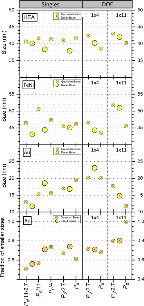
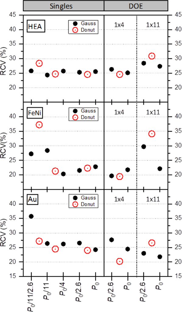
The size distributions of HEA and FeNi NPs can be reasonably fitted with a single lognormal function (Figures 2 and 3 and Supporting Information Files 1 and 2), and the derived median NP sizes are found to be rather fluence-independent with ⟨D⟩ values of around 41 nm for HEA and 46 nm for FeNi in the studied fluence range of 0.9–12.6 J/cm2, that is, laser powers from P0/11/2.7 to P0 (Figure 8). Similar mean sizes and weak fluence dependencies were observed recently for PLAL-produced HEA NPs [18,48]. The relative variations of the sizes (RCV values) are also practically fixed at ≈0.25 for HEA NPs and ≈0.21 for FeNi NPs with a tendency to increase at low fluences for the latter (Figure 9). A similar trend of increasing the polydispersity index of the FeNi NP distributions with reducing the fluence was obtained in MB-PLAL regimes [36].
Figure 8:
Lognormal fitted median size of HEA, FeNi, and Au NPs produced under various PLAL conditions as a function of the total laser power. For gold, the size is given for the small NP population and the fraction of smaller particles is shown on the bottom panel. For convenience, the results for donut-shaped pulses obtained at a power P are placed between P and P/2.7 (the latter corresponds to the same fluence of a Gaussian pulse at P).
Figure 8:
Lognormal fitted median size of HEA, FeNi, and Au NPs produced under various PLAL conditions as a f...
Figure 9:
Robust coefficient of variation (RCV) derived from the measured particle sizes of HEA, FeNi, and Au NPs produced under various PLAL conditions as a function of the total laser power. As in Figure 8, the results with donut-shaped pulses are placed between P and P/2.7.
Figure 9:
Robust coefficient of variation (RCV) derived from the measured particle sizes of HEA, FeNi, and Au...
Gold NPs, however, demonstrate a different behavior. Their median sizes are significantly lower than those of HEA and FeNi NPs, and systematically increase with the fluence from 13 nm at 0.9 J/cm2 to 20 nm at 12.6 J/cm2 (Figure 8). Another difference is that the gold size distributions cannot be adequately described by a single lognormal envelope and clearly exhibit two NP populations, smaller and larger ones (Figure 4, Supporting Information File 2, Figures S10 and S12). Such bimodal size distributions are often observed for noble-metal PLAL-produced NPs [23,25,60,61] and are explained by distinct formation mechanisms for the small and large populations [26,60]. In our case, the small NP population dominates, and its fraction increases with fluence (Figure 8). The RCV values of gold NP distributions are therewith almost fixed at the same value of 0.25 as for HEA NPs throughout the studied fluence range (Figure 9). An exception is at the lowest fluence of 0.9 J/cm2 when the distribution is relatively broad (RCV = 0.35), possibly due to a low pulse-to-pulse reproducibility of the ablation process at the near-threshold fluence.
Splitting the Gaussian beams does not practically affect the size distributions of HEA and FeNi NPs for both 1×4 and 1×11 DOEs (Figure 8 and Figure 9). This indicates that the DOEs, indeed, do not alter the irradiated spot profile and that the interaction of adjacent bubbles simultaneously produced with the 1×4 DOE, if it occurs, has little effect on the size distribution. A slight increase in the median size of FeNi NPs is only observed at the lowest fluence (1×11 DOE, P0/2.7) compared to its single-beam counterpart at P0/11/2.7 (52 nm instead of 46 nm, Figure 8), which can be explained by the poor reproducibility at low fluences. For gold NPs, the situation is again somewhat different. The median size of NPs produced with the 1×4 DOE for both P0 and P0/2.7 is considerably larger (20 nm) than that obtained in the single-beam regimes (15 nm) at the same laser fluences (at P0/4 and P0/4/2.7, respectively). This is likely due to a relatively small separation distance between the spots with the 1×4 DOE, which results in the bubble interaction and affects, in this case, not only the NP synthesis productivity (Section “Productivity”) but also their size distribution.
A question arises: Why are only gold NPs affected by the bubble interaction, while the median sizes of HEA and FeNi NPs remain virtually unchanged under the same MB-PLAL with the 1×4 DOE? One can envision a thermal feedback effect of the neighboring irradiation spots occurring in gold. Indeed, the thermal conductivity of gold (and particularly its electronic component, which dominates at early ablation stages [62]) is much higher than that of alloys [63,64]; thus, interspot heat transfer can result in heat confinement and potentially affect the gold ablation process. According to [62,65], the electronic diffusivity αAu at a typical for picosecond ablation electron temperature of 104 K is ≈500 mm2/s. The corresponding length of the heat diffusion zone (αAuta)1/2 at a time ta of the ablation onset (ta ≈ 100 ps for picosecond-laser ablation [66,67]) is about 0.2 µm, that is, much smaller than both the spot size and spot separation. Therefore, interspot heat transfer can be ruled out under the present conditions, leaving hydrodynamic interaction between the cavitation bubbles as a plausible explanation for the observed effect.
The maximal bubble heights under the considered conditions of picosecond PLAL of gold in water were reported to be 250 µm at 2.7 J/cm2[58], 330 µm at 3.3 J/cm2[57], and 600 µm at 6 J/cm2[57], while, for HEA, the reported bubble height is smaller, ≈100 µm at 5 J/cm2[18] (although the values were obtained at different pulse energies and cannot be compared directly). In any case, the maximal bubble size is smaller than the spot separation in our experiments with the 1×4 DOE (700 µm), and the relevant dimensionless parameter H* (the ratio between double bubble spatial separation and their maximum height, introduced in [58]) is expected to be in the range of 1.5–3.0. At first sight, the bubble interaction should also be ruled out as an explanation of the DOE-induced modification of gold NP sizes since the NP diameters were found to be affected by the interaction of two bubbles only at H* < 1 and remained unaffected in double-pulse PLAL at H* = 1 [58]. However, the situation with multiple bubbles appears to be more complicated, and the bubble interaction occurs even at larger H* values. Thus, Bao et al. [68] investigated the dynamics of three identical, synchronized, symmetrically aligned laser-induced bubbles and demonstrated significant bubble interactions at fairly large separations. It resulted, for instance, in a delay in the evolution of the central bubble with its longer lifetime compared to that of two verge ones even at H* = 3. We believe that such hydrodynamic interaction among bubbles in the MB-PLAL occurs in our experiments with the 1×4 DOE and is a plausible explanation for the observed increase in gold NP sizes. In particular, the extended lifetime of the two central bubbles (serving as NP reactors [69]) allows for NPs to grow to larger sizes, similar to what happens with gold NPs when laser fluence is increased in the single-beam PLAL. This interpretation is also consistent with the relative insensitivity of HEA and FeNi NPs to the beam splitting since the sizes of these NPs are less affected by laser fluence, that is, by the size and lifetime of the cavitation bubble, under the considered conditions (Figure 8).
The RCV values of the distributions are found to be almost unaffected by the beam splitting for all the materials (Figure 9). An exception is again for FeNi NPs at the lowest fluence (1×11 DOE, P0/2.7) when the distribution is broader, probably due to an instability of the ablation process at the near-threshold fluence resulting in a larger variation in sizes of the produced NPs.
Although the observed trends are discussed mainly in terms of the applied fluence relative to the material-specific ablation threshold, the material response is also governed by other thermophysical and optical properties. Thermal conductivity, melting and vaporization enthalpies, optical absorption, and energy coupling to the electron subsystem may influence ablation efficiency, melt ejection, plasma-plume and cavitation-bubble dynamics, and nanoparticle formation. For example, the substantially higher thermal conductivity of Au compared with the investigated alloys may affect energy redistribution and melt dynamics within the irradiated region. Therefore, the different responses of Au, FeNi, and HEA to beam shaping should be attributed to the combined influence of several material properties rather than to the ablation threshold alone. Quantitatively separating their individual contributions is beyond the scope of the present study.
An additional process that apparently influences the size distribution of NPs produced under the considered PLAL conditions, especially in the splitting regimes with the 1×11 DOE, is laser-induced fragmentation in liquids (LFL) [2,70-72]. In LFL, laser-irradiated colloidal NPs absorb laser energy to transiently pass an excited state and finally break into small fragments. The LFL method is used efficiently to produce small, size-controlled NPs from larger NPs [20,46,47,70], often as a separate step in addition to PLAL, and from microparticles [72,73]. LFL can also occur during PLAL synthesis if the produced NPs have a sufficiently long residence time in the irradiation area, but in this case it is considered rather a parasitic process [20] since it is difficult to control both NP growth and fragmentation simultaneously.
The considered splitting in the PLAL regime with 11 sub-beams appears to be favorable for the LFL manifestation. With the setup geometry, the flow direction is parallel to the vertical 11-beam line (Figure S13, Supporting Information File 2). Assuming that the PLAL-produced NPs follow the water flow, their velocity in the chamber can be estimated as 1 m/min. Then the average residence time of the NPs in a 1 cm spiral sub-beam irradiation area is about 0.3 s (estimated for NPs produced in central regions), which corresponds to nearly eight full spiral cycles; thus, the NPs, particularly those originating from the bottom regions, undergo repeated laser exposure. In most cases, the used laser fluences are well above the fragmentation threshold (typically below 1 J/cm2 for picosecond pulses [2,20,72]), and the higher the fluence, the smaller the fragments produced [2]. This is consistent with the increase in the fraction of small gold NPs with increasing fluence (Figure 8, bottom panel). The highest fractions of small Au NPs are observed, in agreement with the above considerations, for the 1×11 splitting regime, exhibiting a unimodal distribution with no statistically resolvable large-particle component at maximal laser power (Figure 8).
We note that LFL is also more likely to occur under single-beam irradiation than in the previous experiments [48]. Here, the chamber volume is five times larger (25 mL instead of 5 mL in [48]) and, with a similar flow rate, this results in a lower removal rate of the produced NPs from the irradiation region, thus giving them a better chance to absorb laser energy. Combined with a longer irradiation time and a high NP synthesis productivity, this represents favorable conditions for LFL. We believe that this is the reason for the difference in the size distributions of gold NPs produced under similar single-beam irradiation conditions, a bimodal distribution in this work and unimodal one in [48].
Donut-shaped beams
As for Gaussian beams, the distributions of donut-beam-generated HEA and FeNi NPs are well described by a single lognormal function, while those for Au NPs exhibit again a bimodal behavior. A single DS beam results generally in smaller HEA and FeNi NPs compared to the corresponding Gaussian pulse (Figure 8), in agreement with the previous observations [48]. This is particularly pronounced at the tails of the distributions where a large-mass cut-off occurs at considerably smaller sizes for DS pulses than for Gaussian pulses, for example, at ≈80 and 90 nm, respectively, for HEA NPs at fairly high fluences (see Figure 2 and Figure S14, Supporting Information File 2). For gold NPs, however, the expected reduction in sizes with the DS pulses is likely masked by the above-discussed LFL processes. As a result, the observed median sizes and fractions of the small population are rather identical for Au NPs produced by single Gaussian and DS pulses (Figure 8).
The RCV values of the NP size distributions obtained with the DS beams are nearly the same as for Gaussian pulses at around 0.25 (Figure 9). Exceptions are observed again at the lowest fluence of 0.9 J/cm2 (power P0/11), when the RCVs are somewhat higher, especially for FeNi NPs (RCV = 0.37), that is, the relative distribution broadening is even stronger than that for the low-fluence Gaussian beam. This is partly due to small median NP sizes under these conditions (note that the smallest sizes of FeNi and Au NPs are obtained here, 43 and 11 nm, respectively, Figure 8). However, other processes, for example, the discussed above NP redeposition at low-fluence DS pulses, can possibly contribute to the observed RCV increase, which requires separate studies.
Splitting the DS beam does not show a distinct reduction in the median NP sizes compared to split Gaussian pulses, as was expected based on experiments with single DS pulses here (Figure 8) and in [48]. The sizes of NPs produced under multidonut-beam conditions are either similar to those obtained in the corresponding Gaussian MB-PLAL or even larger, with similar RCV values (Figure 8). We attribute this behavior to secondary processes occurring or being promoted under multibeam irradiation. Different processes appear to be relevant in the two investigated MB-PLAL configurations. For the 1×4 DOE, the observed behavior is most consistent with cavitation-bubble interaction because the relatively short interspot distance promotes hydrodynamic coupling between neighboring bubbles, as discussed above in the contexts of productivity (Sections “Multibeam approach” and “Donut-shaped beams“) and the sizes of NPs produced with Gaussian beams (Section “Gaussian beams”). The interaction of adjacent cavitation bubbles was shown to modify the NP formation process, leading to increased NP size [58]. However, the present experiments do not allow us to quantify the contribution of this mechanism relative to other secondary processes. For DS beams, the bubble interaction is expected to be stronger than that for Gaussian beams at the same pulse energy and spot separation due to a larger spot size [37]. Indeed, the largest size of gold NPs (whose generation appears to be most affected by the bubble interaction) was observed namely in MB-PLAL with four DS sub-beams (Figure 8). To avoid the NP size modification by the hydrodynamic interaction of the cavitation bubbles and thus to obtain an NP size reduction similar to that with a single DS beam, the sub-beam spot separation should be sufficiently large, presumably larger than the maximal lateral size of the bubble by a factor of at least 3–4 [68]. On the other hand, as pointed out in [58], varying the interspot distance is a distinct novel approach for manipulating the NP size distribution in MB-PLAL.
For the conditions with the 1×11 DOE, the spot separation is large (4 mm), so the bubble interaction, even if it exists, is likely a minor factor. Instead, other processes come into play. The most important one, in particular for gold NPs, as for Gaussian pulses, appears to be LFL due to our PLAL setup with the vertical spot line (Figure S13, Supporting Information File 2). This geometry results in repeated re-irradiation of the generated NPs and in a high fraction of the small Au NP population, which is, however, lower than that with 11 Gaussian beams at the same total power (Figure 8), due to a higher laser fluence in the latter case. The LFL process is expected to be significantly suppressed in the MB-PLAL by using a setup with a horizontal line of the spots and a vertical liquid flow. Such an experiment is currently under preparation. Another possible contributor is NP redeposition, which is expected to be particularly efficient for low-fluence DS pulses, as discussed above in the context of productivity. The relative importance of these processes cannot be, however, determined from the present data and should therefore be regarded as a plausible interpretation. The redeposition process is likely to be size-dependent, but, in contrast to LFL, it leads to an increase of the mean size of the remaining colloidal NPs because larger NPs are shown to be predominantly concentrated at the upper part of the cavitation bubble [74] and thus are less affected by the redeposition. This is, therefore, a plausible explanation of why HEA and FeNi NPs produced with 11 DS sub-beams (and which are apparently less affected by LFL) exhibit the highest median size (Figure 8). An increase of laser fluence in the individual sub-beams would obviously reduce the redeposition effect in this MB-PLAL regime, but this was impossible in our experiments due to limitations of the laser power.
We emphasize that the mechanisms discussed above, including cavitation-bubble interaction, laser-induced fragmentation in liquids, and NP redeposition, should be considered as physically motivated interpretations of the observed trends rather than direct experimental observations. While these mechanisms are consistent with our experimental results and previous reports in the literature, their individual contributions cannot be quantitatively separated using the characterization methods employed in the present study. Direct verification would require dedicated diagnostics, such as time-resolved visualization of the bubble dynamics and in situ studies of NP fragmentation and transport, which are beyond the scope of the present work.
Conclusion
A new approach to advancing laser synthesis of colloidal NPs is proposed by combining the advantages of two recently developed PLAL methods, both of which involve spatial shaping of laser pulses. One method is based on multibeam laser ablation created by splitting a laser beam into several sub-beams, which enables a significant increase in synthesis productivity in a cost-effective way. Another method suggests using donut-shaped laser pulses instead of conventional Gaussian pulses to better control the NP size and morphology. A combination of the methods in one PLAL process is expected to address two main challenges in the use of laser-produced NPs in real-world applications, namely, relatively low synthesis efficiency and insufficient control of the NP size distribution.
In this pilot study, NPs of three materials, gold, an iron–nickel alloy, and a high-entropy alloy, were synthesized by picosecond laser ablation in water using donut-shaped pulses in combination with two MB-PLAL configurations, with 4 and 11 sub-beams. The obtained NPs were compared in terms of productivity and size with those produced by Gaussian pulses and in single-beam PLAL. The experiments were performed over a wide range of laser powers, and we were able to compare single-beam and multibeam PLAL processes at the same pulse energy and fluence per beam.
We have demonstrated that splitting of DS beams into several sub-beams using static DOEs can be as efficient in terms of NP synthesis productivity as that of Gaussian beams. Moreover, at moderate laser fluences (several times the ablation threshold value), DS pulses are found to be even more efficient, possibly because of a larger and more uniformly irradiated ablation spot. At near-threshold fluences, the productivity of DS pulses significantly drops, likely due to redeposition of the ablated material. The obtained productivities of DS-beam-produced HEA and FeNi NPs with the 1×11 DOE are about fourfold higher than those with a single DS beam, that is, the gain in productivity is similar to that observed with Gaussian beams. For gold NPs, the productivity of DS pulses in this MB-PLAL regime is low since fluence is at a near-threshold value even at the maximal laser power. The highest productivity for Au NPs was obtained with the 1×4 DOE and was ≈2.5 times higher than that with a single DS beam. We emphasize that the reported productivity values can be considerably increased in the same MB-PLAL setup by optimization of the laser repetition rates and fluences.
Regarding the NP size distributions, we observe a reduction of the median size of NPs produced by DS pulses in single-beam PLAL in agreement with previous experiments. However, the transfer of this reduction effect to the MB-PLAL configurations is not straightforward and several pitfalls occur due to secondary processes modifying the size distributions. Three processes are identified as potentially important: (a) interaction of individual cavitation bubbles when the interspot distance in MB-PLAL is relatively short; (b) laser fragmentation (in particular, in a non-optimal MB-PLAL configuration, when NPs produced by a sub-beam are repeatedly irradiated by other sub-beams); and (c) NP redeposition (particularly important for low-fluence DS pulses). Mitigation measures to eliminate (or minimize) impacts of the secondary effects are discussed and experiments involving such measures are currently under preparation.
Overall, the results demonstrate that DS beams can be successfully implemented in MB-PLAL without eliminating the productivity advantages of beam splitting. However, achieving simultaneous improvements in productivity and NP size control requires careful optimization of both the optical configuration and the liquid-flow geometry. These findings provide practical guidance for the further development of scalable MB-PLAL systems combining high productivity with improved control over NP size distributions.
Supporting Information
Supporting Information File 1:
Data processing details.
The authors thank Nadezhda M. Bulgakova, Stephan Barcikowski, and Anna R. Ziefuss for useful discussions.
Funding
Rémi Bérard conducts his research under the Marie Skłodowska-Curie Actions – COFUND project, which is co-funded by the European Union (Physics for Future – Grant Agreement No. 101081515). Oleksandr Gatsa and Alexander V. Bulgakov acknowledge support from the European Regional Development Fund and the State Budget of the Czech Republic (project SenDiSo: CZ.02.01.01/00/22_008/0004596). Bilal Gökce acknowledges funding by the Deutsche Forschungsgemeinschaft (DFG, German Research Foundation), grant numbers GO 2566/14-1 and GO 2566/7-2. Rémi Bérard also acknowledges support from COST Action CA23125 TETRA “The mETamaterial foRmalism approach to recognize cAncer” (European Cooperation in Science and Technology).
Amans, D.; Cai, W.; Barcikowski, S. Appl. Surf. Sci.2019,488, 445–454. doi:10.1016/j.apsusc.2019.05.117
Return to citation in text:
[1]
Amendola, V.; Amans, D.; Ishikawa, Y.; Koshizaki, N.; Scirè, S.; Compagnini, G.; Reichenberger, S.; Barcikowski, S. Chem. – Eur. J.2020,26, 9206–9242. doi:10.1002/chem.202000686
Return to citation in text:
[1]
Geoffrion, L. D.; Hesabizadeh, T.; Medina-Cruz, D.; Kusper, M.; Taylor, P.; Vernet-Crua, A.; Chen, J.; Ajo, A.; Webster, T. J.; Guisbiers, G. ACS Omega2020,5, 2660–2669. doi:10.1021/acsomega.9b03172
Return to citation in text:
[1]
Amendola, V.; Guadagnini, A.; Agnoli, S.; Badocco, D.; Pastore, P.; Fracasso, G.; Gerosa, M.; Vurro, F.; Busato, A.; Marzola, P. J. Colloid Interface Sci.2021,596, 332–341. doi:10.1016/j.jcis.2021.03.096
Return to citation in text:
[1]
Scaramuzza, S.; de Faria, C. M. G.; Coviello, V.; Forrer, D.; Artiglia, L.; Badocco, D.; Pastore, P.; Ghigna, P.; Postuma, I.; Cansolino, L.; Ferrari, C.; Bortolussi, S.; Vago, R.; Spinelli, A. E.; Bekić, M.; Čolić, M.; Amendola, V. Adv. Funct. Mater.2023,33, 2303366. doi:10.1002/adfm.202303366
Return to citation in text:
[1]
Forsythe, R. C.; Cox, C. P.; Wilsey, M. K.; Müller, A. M. Chem. Rev.2021,121, 7568–7637. doi:10.1021/acs.chemrev.0c01069
Return to citation in text:
[1]
Matten, M.; Koch, N. G.; Caidi, A.; Radev, I.; Lange, T.; Barcikowski, S.; Reichenberger, S. J. Phys. Chem. C2025,129, 7740–7750. doi:10.1021/acs.jpcc.5c00223
Return to citation in text:
[1]
Ji, S.; Li, P.; Zhao, X.; Wei, S.; Cheng, X.; Wu, L.; Ye, Y.; Ma, K.; Cai, Y.; Liang, C. Sens. Actuators, B2023,383, 133595. doi:10.1016/j.snb.2023.133595
Return to citation in text:
[1]
Cortes, F. R. U.; Falomir, E.; Lancis, J.; Mínguez-Vega, G. Appl. Surf. Sci.2024,665, 160326. doi:10.1016/j.apsusc.2024.160326
Return to citation in text:
[1]
Hupfeld, T.; Wegner, A.; Blanke, M.; Doñate‐Buendía, C.; Sharov, V.; Nieskens, S.; Piechotta, M.; Giese, M.; Barcikowski, S.; Gökce, B. Adv. Opt. Mater.2020,8, 2000473. doi:10.1002/adom.202000473
Return to citation in text:
[1]
Logunov, L.; Ulesov, A.; Khramenkova, V.; Liu, X.; Kuchmizhak, A. A.; Vinogradov, A.; Makarov, S. Nanomaterials2023,13, 965. doi:10.3390/nano13060965
Return to citation in text:
[1]
Chausali, N.; Saxena, J.; Prasad, R. J. Agric. Food Res.2023,12, 100541. doi:10.1016/j.jafr.2023.100541
Return to citation in text:
[1]
Kosajan, V.; Wen, Z.; Wang, X. J. Ind. Ecol.2025,29, 344–357. doi:10.1111/jiec.13601
Return to citation in text:
[1]
Bulgakov, A. V.; Bulgakova, N. M. Sci. China: Phys., Mech. Astron.2022,65, 274207. doi:10.1007/s11433-021-1858-9
Return to citation in text:
[1]
Streubel, R.; Barcikowski, S.; Gökce, B. Opt. Lett.2016,41, 1486–1489. doi:10.1364/ol.41.001486
Return to citation in text:
[1]
[2]
[3]
Gatsa, O.; Tahir, S.; Flimelová, M.; Riahi, F.; Doñate-Buendia, C.; Gökce, B.; Bulgakov, A. V. Nanomaterials2024,14, 365. doi:10.3390/nano14040365
Return to citation in text:
[1]
[2]
[3]
[4]
[5]
[6]
[7]
[8]
[9]
[10]
[11]
[12]
[13]
[14]
Kalus, M.-R.; Reimer, V.; Barcikowski, S.; Gökce, B. Appl. Surf. Sci.2019,465, 1096–1102. doi:10.1016/j.apsusc.2018.09.224
Return to citation in text:
[1]
Ziefuss, A. R.; Reich, S.; Reichenberger, S.; Levantino, M.; Plech, A. Phys. Chem. Chem. Phys.2020,22, 4993–5001. doi:10.1039/c9cp05202j
Return to citation in text:
[1]
[2]
[3]
[4]
Spellauge, M.; Redka, D.; Podhrazsky, A.; Eckmann, K.; Eulenkamp, C.; Koepp, O.; Doñate-Buendia, C.; Gökce, B.; Barcikowski, S.; Huber, H. P. Laser Photonics Rev.2026,20, e01348. doi:10.1002/lpor.202501348
Return to citation in text:
[1]
[2]
[3]
Doñate-Buendía, C.; Fernández-Alonso, M.; Lancis, J.; Mínguez-Vega, G. Photonics Res.2019,7, 1249–1257. doi:10.1364/prj.7.001249
Return to citation in text:
[1]
[2]
Sylvestre, J.-P.; Kabashin, A. V.; Sacher, E.; Meunier, M. Appl. Phys. A: Mater. Sci. Process.2005,80, 753–758. doi:10.1007/s00339-004-3081-4
Return to citation in text:
[1]
[2]
Zhang, D. S.; Li, Z. G.; Liang, C. H. Sci. China: Phys., Mech. Astron.2022,65, 274203. doi:10.1007/s11433-021-1860-x
Return to citation in text:
[1]
Shih, C.-Y.; Streubel, R.; Heberle, J.; Letzel, A.; Shugaev, M. V.; Wu, C.; Schmidt, M.; Gökce, B.; Barcikowski, S.; Zhigilei, L. V. Nanoscale2018,10, 6900–6910. doi:10.1039/c7nr08614h
Return to citation in text:
[1]
[2]
Shih, C.-Y.; Shugaev, M. V.; Wu, C.; Zhigilei, L. V. Phys. Chem. Chem. Phys.2020,22, 7077–7099. doi:10.1039/d0cp00608d
Return to citation in text:
[1]
[2]
Sajti, C. L.; Sattari, R.; Chichkov, B. N.; Barcikowski, S. J. Phys. Chem. C2010,114, 2421–2427. doi:10.1021/jp906960g
Return to citation in text:
[1]
Cristoforetti, G.; Pitzalis, E.; Spiniello, R.; Ishak, R.; Muniz-Miranda, M. J. Phys. Chem. C2011,115, 5073–5083. doi:10.1021/jp109281q
Return to citation in text:
[1]
Intartaglia, R.; Bagga, K.; Brandi, F. Opt. Express2014,22, 3117–3127. doi:10.1364/oe.22.003117
Return to citation in text:
[1]
Khairani, I. Y.; Mínguez-Vega, G.; Doñate-Buendía, C.; Gökce, B. Phys. Chem. Chem. Phys.2023,25, 19380–19408. doi:10.1039/d3cp01214j
Return to citation in text:
[1]
Messina, G. C.; Wagener, P.; Streubel, R.; De Giacomo, A.; Santagata, A.; Compagnini, G.; Barcikowski, S. Phys. Chem. Chem. Phys.2013,15, 3093–3098. doi:10.1039/c2cp42626a
Return to citation in text:
[1]
Monsa, Y.; Gal, G.; Lerner, N.; Bar, I. Nanotechnology2020,31, 235601. doi:10.1088/1361-6528/ab78ac
Return to citation in text:
[1]
Mansour, Y.; Battie, Y.; Naciri, A. E.; Chaoui, N. Nanotechnology2023,34, 075602. doi:10.1088/1361-6528/aca3b0
Return to citation in text:
[1]
Barcikowski, S.; Menéndez-Manjón, A.; Chichkov, B.; Brikas, M.; Račiukaitis, G. Appl. Phys. Lett.2007,91, 083113. doi:10.1063/1.2773937
Return to citation in text:
[1]
Semaltianos, N. G. Crit. Rev. Solid State Mater. Sci.2010,35, 105–124. doi:10.1080/10408431003788233
Return to citation in text:
[1]
Khairani, I. Y.; Spellauge, M.; Riahi, F.; Huber, H. P.; Gökce, B.; Doñate-Buendía, C. Adv. Photonics Res.2024,5, 2300290. doi:10.1002/adpr.202300290
Return to citation in text:
[1]
[2]
[3]
[4]
Molina-Prados, S.; Bulgakova, N. M.; Bulgakov, A. V.; Lancis, J.; Vega, G. M.; Doñate-Buendia, C. Beilstein J. Nanotechnol.2026,17, 309–342. doi:10.3762/bjnano.17.22
Return to citation in text:
[1]
[2]
[3]
[4]
[5]
[6]
[7]
[8]
Sobhan, M. A.; Ams, M.; Withford, M. J.; Goldys, E. M. J. Nanopart. Res.2010,12, 2831–2842. doi:10.1007/s11051-010-9868-7
Return to citation in text:
[1]
Hamad, A.; Li, L.; Liu, Z. Appl. Phys. A: Mater. Sci. Process.2015,120, 1247–1260. doi:10.1007/s00339-015-9326-6
Return to citation in text:
[1]
Mafuné, F.; Kohno, J.-y.; Takeda, Y.; Kondow, T. J. Phys. Chem. B2002,106, 7575–7577. doi:10.1021/jp020577y
Return to citation in text:
[1]
Essaidi, A.; Chakif, M.; Schöps, B.; Aumman, A.; Xiao, S.; Esen, C.; Ostendorf, A. J. Laser Micro/Nanoeng.2013,8, 131–136. doi:10.2961/jlmn.2013.02.0003
Return to citation in text:
[1]
Gao, C.; Vuong, J.; Zhang, Q.; Liu, Y.; Yin, Y. Nanoscale2012,4, 2875–2878. doi:10.1039/c2nr30300k
Return to citation in text:
[1]
Sylvestre, J.-P.; Kabashin, A. V.; Sacher, E.; Meunier, M.; Luong, J. H. T. J. Am. Chem. Soc.2004,126, 7176–7177. doi:10.1021/ja048678s
Return to citation in text:
[1]
Rehbock, C.; Merk, V.; Gamrad, L.; Streubel, R.; Barcikowski, S. Phys. Chem. Chem. Phys.2013,15, 3057–3067. doi:10.1039/c2cp42641b
Return to citation in text:
[1]
Besner, S.; Kabashin, A. V.; Winnik, F. M.; Meunier, M. Appl. Phys. A: Mater. Sci. Process.2008,93, 955–959. doi:10.1007/s00339-008-4773-y
Return to citation in text:
[1]
[2]
Luo, R.-C.; Li, C.; Du, X.-W.; Yang, J. Angew. Chem., Int. Ed.2015,54, 4787–4791. doi:10.1002/anie.201411322
Return to citation in text:
[1]
[2]
[3]
Altakroury, A. R.; Gatsa, O.; Riahi, F.; Fu, Z.; Flimelová, M.; Samokhvalov, A.; Barcikowski, S.; Doñate-Buendía, C.; Bulgakov, A. V.; Gökce, B. Beilstein J. Nanotechnol.2025,16, 407–417. doi:10.3762/bjnano.16.31
Return to citation in text:
[1]
[2]
[3]
[4]
[5]
[6]
[7]
[8]
[9]
[10]
Tang, Y.; Perrie, W.; Rico Sierra, D.; Li, Q.; Liu, D.; Edwardson, S. P.; Dearden, G. Micromachines2021,12, 376. doi:10.3390/mi12040376
Return to citation in text:
[1]
Tahir, S.; Shkodich, N.; Eggert, B.; Lill, J.; Gatsa, O.; Flimelová, M.; Adabifiroozjaei, E.; Bulgakova, N. M.; Molina‐Luna, L.; Wende, H.; Farle, M.; Bulgakov, A. V.; Doñate‐Buendía, C.; Gökce, B. ChemNanoMat2024,10, e202400064. doi:10.1002/cnma.202400064
Return to citation in text:
[1]
[2]
Arachchige, C. N. P. G.; Prendergast, L. A.; Staudte, R. G. J. Appl. Stat.2022,49, 268–290. doi:10.1080/02664763.2020.1808599
Return to citation in text:
[1]
Neuenschwander, B.; Jaeggi, B.; Schmid, M.; Hennig, G. Phys. Procedia2014,56, 1047–1058. doi:10.1016/j.phpro.2014.08.017
Return to citation in text:
[1]
Jee, Y.; Becker, M. F.; Walser, R. M. J. Opt. Soc. Am. B1988,5, 648–659. doi:10.1364/josab.5.000648
Return to citation in text:
[1]
Raciukaitis, G.; Brikas, M.; Gecys, P.; Gedvilas, M. Proc. SPIE2008,7005, 70052L. doi:10.1117/12.782937
Return to citation in text:
[1]
[2]
Armbruster, O.; Naghilou, A.; Kitzler, M.; Kautek, W. Appl. Surf. Sci.2017,396, 1736–1740. doi:10.1016/j.apsusc.2016.11.229
Return to citation in text:
[1]
Gamaly, E. G.; Madsen, N. R.; Duering, M.; Rode, A. V.; Kolev, V. Z.; Luther-Davies, B. Phys. Rev. B2005,71, 174405. doi:10.1103/physrevb.71.174405
Return to citation in text:
[1]
Tomko, J.; Naddeo, J. J.; Jimenez, R.; Tan, Y.; Steiner, M.; Fitz-Gerald, J. M.; Bubb, D. M.; O'Malley, S. M. Phys. Chem. Chem. Phys.2015,17, 16327–16333. doi:10.1039/c5cp01965f
Return to citation in text:
[1]
[2]
[3]
Riahi, F.; Bußmann, A.; Doñate-Buendia, C.; Adami, S.; Adams, N. A.; Barcikowski, S.; Gökce, B. Photonics Res.2023,11, 2054–2071. doi:10.1364/prj.498204
Return to citation in text:
[1]
[2]
[3]
[4]
[5]
[6]
[7]
Doan, H. D.; Iwatani, N.; Sasaki, H.; Matsumura, S.; Fushinobu, K. Nanosecond time-resolved visualization of short pulse laser ablation processes for various laser beam profiles. Proc. 14th IEEE Int. Conf. on Thermal and Thermomechanical Phenomena in Electronic Systems (ITherm), Orlando, FL, USA; 2014; pp 1279–1284. doi:10.1109/itherm.2014.6892428
Return to citation in text:
[1]
Inasawa, S.; Sugiyama, M.; Yamaguchi, Y. J. Phys. Chem. B2005,109, 9404–9410. doi:10.1021/jp0441240
Return to citation in text:
[1]
[2]
Marzun, G.; Nakamura, J.; Zhang, X.; Barcikowski, S.; Wagener, P. Appl. Surf. Sci.2015,348, 75–84. doi:10.1016/j.apsusc.2015.01.108
Return to citation in text:
[1]
Lin, Z.; Zhigilei, L. V.; Celli, V. Phys. Rev. B2008,77, 075133. doi:10.1103/physrevb.77.075133
Return to citation in text:
[1]
[2]
Ho, C. Y.; Ackerman, M. W.; Wu, K. Y.; Oh, S. G.; Havill, T. N. J. Phys. Chem. Ref. Data1978,7, 959–1178. doi:10.1063/1.555583
Return to citation in text:
[1]
He, M.; Wu, C.; Shugaev, M. V.; Samolyuk, G. D.; Zhigilei, L. V. J. Phys. Chem. C2019,123, 2202–2215. doi:10.1021/acs.jpcc.8b09922
Return to citation in text:
[1]
Lizunov, S. A.; Bulgakov, A. V.; Campbell, E. E. B.; Bulgakova, N. M. Appl. Phys. A: Mater. Sci. Process.2022,128, 602. doi:10.1007/s00339-022-05733-4
Return to citation in text:
[1]
Carrasco-García, I.; Vadillo, J. M.; Laserna, J. J. J. Anal. At. Spectrom.2019,34, 2119–2125. doi:10.1039/c9ja00196d
Return to citation in text:
[1]
Bao, H.; Zhang, H.; Gao, L.; Tang, M.; Zhang, C.; Lu, J. Ultrason. Sonochem.2021,71, 105375. doi:10.1016/j.ultsonch.2020.105375
Return to citation in text:
[1]
[2]
Rehbock, C.; Jakobi, J.; Gamrad, L.; van der Meer, S.; Tiedemann, D.; Taylor, U.; Kues, W.; Rath, D.; Barcikowski, S. Beilstein J. Nanotechnol.2014,5, 1523–1541. doi:10.3762/bjnano.5.165
Return to citation in text:
[1]
González-Rubio, G.; Guerrero-Martínez, A.; Liz-Marzán, L. M. Acc. Chem. Res.2016,49, 678–686. doi:10.1021/acs.accounts.6b00041
Return to citation in text:
[1]
[2]
Huang, H.; Zhigilei, L. V. J. Phys. Chem. C2021,125, 13413–13432. doi:10.1021/acs.jpcc.1c03146
Return to citation in text:
[1]
Spellauge, M.; Auer, R.; Tack, M.; Limani, F.; Redka, D.; Reichenberger, S.; Ziefuss, A. R.; Barcikowski, S.; Huber, H. P. Opt. Laser Technol.2026,203, 115762. doi:10.1016/j.optlastec.2026.115762
Return to citation in text:
[1]
[2]
[3]
Spellauge, M.; Auer, R.; Tack, M.; Limani, F.; Redka, D.; Reichenberger, S.; Ziefuss, A. R.; Barcikowski, S.; Huber, H. P. Opt. Laser Technol.2026,203, 115762. doi:10.1016/j.optlastec.2026.115762
Ziefuss, A. R.; Reich, S.; Reichenberger, S.; Levantino, M.; Plech, A. Phys. Chem. Chem. Phys.2020,22, 4993–5001. doi:10.1039/c9cp05202j
72.
Spellauge, M.; Auer, R.; Tack, M.; Limani, F.; Redka, D.; Reichenberger, S.; Ziefuss, A. R.; Barcikowski, S.; Huber, H. P. Opt. Laser Technol.2026,203, 115762. doi:10.1016/j.optlastec.2026.115762
Spellauge, M.; Auer, R.; Tack, M.; Limani, F.; Redka, D.; Reichenberger, S.; Ziefuss, A. R.; Barcikowski, S.; Huber, H. P. Opt. Laser Technol.2026,203, 115762. doi:10.1016/j.optlastec.2026.115762
Gatsa, O.; Tahir, S.; Flimelová, M.; Riahi, F.; Doñate-Buendia, C.; Gökce, B.; Bulgakov, A. V. Nanomaterials2024,14, 365. doi:10.3390/nano14040365
36.
Khairani, I. Y.; Spellauge, M.; Riahi, F.; Huber, H. P.; Gökce, B.; Doñate-Buendía, C. Adv. Photonics Res.2024,5, 2300290. doi:10.1002/adpr.202300290
37.
Molina-Prados, S.; Bulgakova, N. M.; Bulgakov, A. V.; Lancis, J.; Vega, G. M.; Doñate-Buendia, C. Beilstein J. Nanotechnol.2026,17, 309–342. doi:10.3762/bjnano.17.22
Gatsa, O.; Tahir, S.; Flimelová, M.; Riahi, F.; Doñate-Buendia, C.; Gökce, B.; Bulgakov, A. V. Nanomaterials2024,14, 365. doi:10.3390/nano14040365
57.
Tomko, J.; Naddeo, J. J.; Jimenez, R.; Tan, Y.; Steiner, M.; Fitz-Gerald, J. M.; Bubb, D. M.; O'Malley, S. M. Phys. Chem. Chem. Phys.2015,17, 16327–16333. doi:10.1039/c5cp01965f
Gatsa, O.; Tahir, S.; Flimelová, M.; Riahi, F.; Doñate-Buendia, C.; Gökce, B.; Bulgakov, A. V. Nanomaterials2024,14, 365. doi:10.3390/nano14040365
36.
Khairani, I. Y.; Spellauge, M.; Riahi, F.; Huber, H. P.; Gökce, B.; Doñate-Buendía, C. Adv. Photonics Res.2024,5, 2300290. doi:10.1002/adpr.202300290
37.
Molina-Prados, S.; Bulgakova, N. M.; Bulgakov, A. V.; Lancis, J.; Vega, G. M.; Doñate-Buendia, C. Beilstein J. Nanotechnol.2026,17, 309–342. doi:10.3762/bjnano.17.22
Molina-Prados, S.; Bulgakova, N. M.; Bulgakov, A. V.; Lancis, J.; Vega, G. M.; Doñate-Buendia, C. Beilstein J. Nanotechnol.2026,17, 309–342. doi:10.3762/bjnano.17.22
Gatsa, O.; Tahir, S.; Flimelová, M.; Riahi, F.; Doñate-Buendia, C.; Gökce, B.; Bulgakov, A. V. Nanomaterials2024,14, 365. doi:10.3390/nano14040365
37.
Molina-Prados, S.; Bulgakova, N. M.; Bulgakov, A. V.; Lancis, J.; Vega, G. M.; Doñate-Buendia, C. Beilstein J. Nanotechnol.2026,17, 309–342. doi:10.3762/bjnano.17.22
Doan, H. D.; Iwatani, N.; Sasaki, H.; Matsumura, S.; Fushinobu, K. Nanosecond time-resolved visualization of short pulse laser ablation processes for various laser beam profiles. Proc. 14th IEEE Int. Conf. on Thermal and Thermomechanical Phenomena in Electronic Systems (ITherm), Orlando, FL, USA; 2014; pp 1279–1284. doi:10.1109/itherm.2014.6892428
Molina-Prados, S.; Bulgakova, N. M.; Bulgakov, A. V.; Lancis, J.; Vega, G. M.; Doñate-Buendia, C. Beilstein J. Nanotechnol.2026,17, 309–342. doi:10.3762/bjnano.17.22
48.
Altakroury, A. R.; Gatsa, O.; Riahi, F.; Fu, Z.; Flimelová, M.; Samokhvalov, A.; Barcikowski, S.; Doñate-Buendía, C.; Bulgakov, A. V.; Gökce, B. Beilstein J. Nanotechnol.2025,16, 407–417. doi:10.3762/bjnano.16.31
Molina-Prados, S.; Bulgakova, N. M.; Bulgakov, A. V.; Lancis, J.; Vega, G. M.; Doñate-Buendia, C. Beilstein J. Nanotechnol.2026,17, 309–342. doi:10.3762/bjnano.17.22
Gatsa, O.; Tahir, S.; Flimelová, M.; Riahi, F.; Doñate-Buendia, C.; Gökce, B.; Bulgakov, A. V. Nanomaterials2024,14, 365. doi:10.3390/nano14040365
36.
Khairani, I. Y.; Spellauge, M.; Riahi, F.; Huber, H. P.; Gökce, B.; Doñate-Buendía, C. Adv. Photonics Res.2024,5, 2300290. doi:10.1002/adpr.202300290
37.
Molina-Prados, S.; Bulgakova, N. M.; Bulgakov, A. V.; Lancis, J.; Vega, G. M.; Doñate-Buendia, C. Beilstein J. Nanotechnol.2026,17, 309–342. doi:10.3762/bjnano.17.22
Molina-Prados, S.; Bulgakova, N. M.; Bulgakov, A. V.; Lancis, J.; Vega, G. M.; Doñate-Buendia, C. Beilstein J. Nanotechnol.2026,17, 309–342. doi:10.3762/bjnano.17.22
48.
Altakroury, A. R.; Gatsa, O.; Riahi, F.; Fu, Z.; Flimelová, M.; Samokhvalov, A.; Barcikowski, S.; Doñate-Buendía, C.; Bulgakov, A. V.; Gökce, B. Beilstein J. Nanotechnol.2025,16, 407–417. doi:10.3762/bjnano.16.31
Tomko, J.; Naddeo, J. J.; Jimenez, R.; Tan, Y.; Steiner, M.; Fitz-Gerald, J. M.; Bubb, D. M.; O'Malley, S. M. Phys. Chem. Chem. Phys.2015,17, 16327–16333. doi:10.1039/c5cp01965f
Tomko, J.; Naddeo, J. J.; Jimenez, R.; Tan, Y.; Steiner, M.; Fitz-Gerald, J. M.; Bubb, D. M.; O'Malley, S. M. Phys. Chem. Chem. Phys.2015,17, 16327–16333. doi:10.1039/c5cp01965f