

Search results
Search for "ethylenediamine" in Full Text gives 73 result(s) in Beilstein Journal of Organic Chemistry.
Rh(III)-catalyzed chelation-assisted C–H activation/annulation of 2-arylimidazolines with cyclic diazo-1,3-dicarbonyl compounds: a novel approach to tetracyclic annulated derivatives of 2,3-dihydroimidazo[2,1-a]isoquinoline
- Ivan Lyutin,
- Grigory Kantin,
- Olga Bakulina and
- Dmitry Dar'in
Beilstein J. Org. Chem. 2026, 22, 997–1003, doi:10.3762/bjoc.22.78
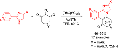
- azides, while 2-arylimidazolines 2 were prepared via condensation of aromatic aldehydes with ethylenediamine in the presence of N-bromosuccinimide [25]. We began our investigation with the model reaction of 2-(4-chlorophenyl)imidazoline (2a) with 2-diazodimedone (3a), which resulted in the formation of

Graphical Abstract

Figure 1: a,b) Structure of biologically active 2,3-dihydroimidazo[2,1-a]isoquinolines (1) and their publishe...

Scheme 1: C–H activation/annulation of 2-arylimidazolines with diazo-1,3-dicarbonyl compounds. aReaction cond...

Figure 2: Structures of products from unsuccessful reactions of 2-arylimidazolines with diazo 1,3-dicarbonyl ...

Figure 3: a) Proposed reaction mechanism; b) Experimental isolation of intermediate B (compound 5) from equim...
Synthesis and structural elucidation of a novel bis-spirooxindole from isatin and ethylenediamine
- Irene Moreno-Gutiérrez,
- Josefa L. López-Martínez,
- Sonia Berenguel-Gómez,
- Irene Torres-García,
- Duane Choquesillo-Lazarte,
- Manuel Muñoz-Dorado,
- Miriam Álvarez-Corral and
- Ignacio Rodríguez-García
Beilstein J. Org. Chem. 2026, 22, 813–820, doi:10.3762/bjoc.22.63

- , IACT-CSIC. Avda. de las Palmeras 4, 18100 Armilla (Granada), Spain 10.3762/bjoc.22.63 Abstract The reactivity of isatin toward ethylenediamine displays an unexpected stoichiometric divergence, affording either the anticipated diiminoisatin or a previously unreported pentacyclic bis-spirooxindole. A 2
- conditions. Keywords: ethylenediamine; isatin; spirooxindole; Introduction Isatin (1) is a highly versatile platform for heterocycle construction, particularly through skeletal editing, ring expansion, and related transformations that enable rapid access to complex molecular architectures [1]. In parallel
- . In this context, we turned our attention to the reaction of isatin with unsubstituted ethylenediamine. Although analogy with related diamines would suggest preferential diiminoisatin formation, our results reveal a pronounced divergence in reactivity under different conditions, prompting a detailed

Graphical Abstract

Figure 1: Isatin and representative bioactive spiro-fused 2-oxindoles.

Scheme 1: Reaction of isatin (1) with ʟ-proline (7) [16,17].

Scheme 2: Condensations of isatin with primary [18] and N-methylated diamines [19].

Scheme 3: Catalyzed synthesis of the bis[spiro(quinazoline-oxindole)] derivative 21 [20].

Scheme 4: (a) Ethylenediamine (0.5 equiv), MeOH, reflux, 5 h, 66%; (b) ethylenediamine (2 equiv), EtOH, reflu...

Figure 2: ORTEP representation of bis-spirooxindole 25 (ellipsoids at 50% probability), showing the C2-symmet...

Scheme 5: Proposed mechanism for the formation of 25.

Scheme 6: Synthesis of 30 from 5-methylisatin (29).
Hydrogen production from formic acid catalyzed by NHC–Cu complexes
- Orlando Santoro and
- Catherine S. J. Cazin
Beilstein J. Org. Chem. 2026, 22, 620–627, doi:10.3762/bjoc.22.48
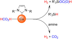
- conversion was obtained with respect to the reaction involving triethylamine (Table 2, entries 2 and 3). Upon employing ethylenediamine, the conversion dropped to 26% (Table 2, entry 4). This may be due to the chelating behavior of this amine. Indeed, ethylenediamine can strongly coordinate the metal center

Graphical Abstract

Figure 1: NHC–Cu complexes investigated in this study.

Scheme 1: Hypothetical mechanism for FA decomposition via decarboxylation of NHC–Cu–formato species.

Figure 2: Decomposition of FA catalyzed by NHC–Cu complexes in the presence of PhSiH3. Reaction conditions: f...

Figure 3: Decomposition of FA catalyzed by NHC–Cu complexes in the presence of different silanes. Reaction co...

Scheme 2: Isotopic labeling experiments.
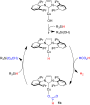
Scheme 3: Proposed catalytic cycle for the NHC–Cu-catalyzed FA dehydrogenation.

Scheme 4: Dehydrogenative coupling of phenylsilane.
Modern synthetic pathways towards eribulin and its subunits
- Sebastian Dominik Graf
Beilstein J. Org. Chem. 2026, 22, 495–526, doi:10.3762/bjoc.22.37
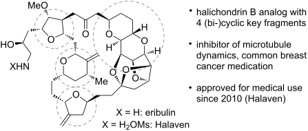

Graphical Abstract

Figure 1: Eribulin with common synthetic precursor fragments and halichondrin B.

Scheme 1: Overview of the industrial process pathway for the large-scale production of the mesylate salt of 1...

Scheme 2: Synthesis of 22. (a) i. 2,2-dimethoxypropane, p-TsOH, MeOH, 65 °C; ii. NaBH4, MeOH, rt; (b) i. NaH,...

Scheme 3: Synthesis of 27. (a) i. NaH, BnBr, THF, rt; ii. iodobenzoic acid, MeCN, 80 °C; iii. (EtO)2POCH2COOE...

Scheme 4: Synthesis of 31 and 33. (a) i. MMTrCl, iPr2NEt, DCM, rt; ii. K2CO3, MeOH, DCM, rt; iii. TBDMSCl, im...

Scheme 5: Synthesis of 1. (a) CrCl2, 37, 38, 39 (proton sponge), LiCl, Mn, ZrCp2Cl2, MeCN, EtOAc; (b) SrCO3, t...

Scheme 6: Synthesis of 45. Above: Reaction conditions: (a) methoxyacetic acid, BF3·OEt2, DCM, −30 °C; (b) Pd(...

Scheme 7: Synthesis of 64. Reaction conditions: (a) i. acetone, I2, rt; ii. vinylmagnesium bromide, THF, −20 ...
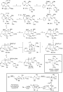
Scheme 8: Synthesis of 79. Above: Reaction conditions: (a) i. K2CO3, MeOH, 60 °C; ii. 2,2-dimethoxypropane, H2...

Scheme 9: Synthesis of 92. Reaction conditions: (a) TESCl, imidazole, DCM, 0 °C to rt; (b) i. oxalyl chloride...
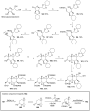
Scheme 10: Synthesis of 104. Above: Reaction conditions: (a) cyclohexanone, p-TsOH, toluene, 110 °C, crystalli...

Scheme 11: Synthesis of 117. (a) i. acetone, CuSO4, rt; ii. H2O2, K2CO3, H2O, rt; iii. EtI, MeCN, 70 °C; (b) i...

Scheme 12: Synthesis of 121. Reaction conditions: (a) i. TBDPSCl, imidazole, DMF, rt; ii. O3, DCM, −78 °C; iii...

Scheme 13: Synthesis of 131. (a) i. 2,2-dimethoxypropane, p-TsOH, MeOH, 60 °C; ii. LiAlH4, THF, 0 °C to rt; (b...

Scheme 14: Synthesis of 143. (a) i. I2, PPh3, imidazole, DCM; ii. HMPA, CuI, vinylmagnesium bromide, THF, −20 ...

Scheme 15: Modified synthesis of 104. Reaction conditions: (a) (EtO)2POCH2COOEt, KOt-Bu, THF, 15 °C; (b) TBAF,...

Scheme 16: Synthesis of 161. Reaction conditions: (a) crotyl bromide, Sn, TBAI, NaI, DMF/H2O, rt; (b) NaH, BnB...

Scheme 17: Synthesis of 169. Reaction conditions: (a) i. Co2(CO)8, BF3·Et2O, DCM, 23 °C; ii. CAN, acetone, 0 °...

Scheme 18: Synthesis of 181. Reaction conditions: (a) i. Co2(CO)8, BF3·Et2O, DCM, 23 °C; ii. (NH4)2Ce(NO3)6, a...

Scheme 19: Synthesis of 186. Reaction conditions: (a) NEt3, LiCl, MeCN, 0–23 °C; (b) HF·pyridine, MeCN, 23 °C;...

Scheme 20: Modified synthesis of 181. Reaction conditions: (a) i. Ni(cod)2, P(n-Bu)3, Et3SiH, THF, 23 °C; ii. ...

Scheme 21: Synthesis of 200. Reaction conditions: (a) i. Co2(CO)8, DCM, 23 °C; ii. BF3·Et2O, 0 °C; iii. (NH4)2...

Scheme 22: Modified synthesis of 186. Reaction conditions: (a) DDQ, 2,6-di-t-Bu-4-hydroxytoluene, hv, MeCN, 23...

Scheme 23: Synthesis of 1. Reaction conditions: (a) i. CrCl2, NiCl2, 206, NEt3, THF, 23 °C; ii. DBU, toluene, ...

Scheme 24: Synthesis of 217. Above: Reaction conditions: (a) TBDPSCl, imidazole, DCM, 0–5 °C. (b) m-CPBA, DCM,...

Scheme 25: Synthesis of 231. Reaction conditions: (a) i. AcCl, MeOH, 0 °C to rt; ii. TrCl, pyridine, 50 °C; (b...

Scheme 26: Synthesis of 239. Reaction conditions: (a) i. Boc2O, K2CO3, THF, rt; ii. Ru(acac)3, NaBrO3, EtOAc, H...

Scheme 27: Synthesis of 247. Reaction conditions: (a) NCS, 248, MeCN, 0 °C to rt; (b) LDA, 249, THF, −78 °C; (...

Scheme 28: Synthesis of 255. Reaction conditions: (a) i. LiHMDS, THF, −78 °C to rt; ii. m-CPBA, DCM, −78 °C to...

Scheme 29: Synthesis of 261. Reaction conditions: (a) allyltrimethylsilane, TiCl4, DCM −78 °C; (b) LiBH4, EtOH...

Scheme 30: Synthesis of 265. Reaction conditions: (a) (R,R)-Ru-cat (0.2 mol %), DCM, NEt3, HCOOH, rt; (b) TBAF...

Scheme 31: Synthesis of 272. Reaction conditions: (a) LDA, THF, −78 °C; (b) DMP, NaHCO3, DCM, 0 °C to rt; (c) (...
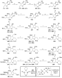
Scheme 32: Synthesis of 292. Reaction conditions: (a) TsCl, NEt3, DCM, rt; (b) K2CO3, MeOH, 45 °C; (c) vinylma...

Scheme 33: Synthesis of 296. Reaction conditions: (a) 171 (see Scheme 17), Cr-cat, CoPc (see Scheme 17), Mn, NEt3·HCl, LiCl, TMS...

Scheme 34: Synthesis of 299. Reaction conditions: (a) 172 (see Scheme 17), CrCl2, NEt3, NiCl2, THF, rt; (b) KHMDS, THF,...

Scheme 35: Synthesis of 305. Reaction conditions: (a) i. p-TsOH, MeOH, 40 °C; ii. MeLi, LiBr, THF, −25 °C; (b)...
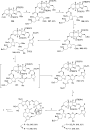
Scheme 36: Synthesis of 1. Reaction conditions: (a) i. 41 (see Scheme 6), LDA, THF, −78 °C; ii. DMP, NaHCO3, DCM, rt; ...

Scheme 37: Synthesis of 324. Reaction conditions: (a) i. acetone, CuSO4, rt; ii. H2O2 (30%), K2CO3, rt; iii. E...
Competitive cyclization of ethyl trifluoroacetoacetate and methyl ketones with 1,3-diamino-2-propanol into hydrogenated oxazolo- and pyrimido-condensed pyridones
- Svetlana O. Kushch,
- Marina V. Goryaeva,
- Yanina V. Burgart,
- Marina A. Ezhikova,
- Mikhail I. Kodess,
- Pavel A. Slepukhin,
- Alexandrina S. Volobueva,
- Vladimir V. Zarubaev and
- Victor I. Saloutin
Beilstein J. Org. Chem. 2025, 21, 2716–2729, doi:10.3762/bjoc.21.209
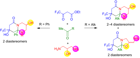
- ethylenediamine [27] as well as with 2-(aminomethyl)aniline and 1,3-diaminopropane [28]. In addition, we have found another route for the three-component cyclization of 3-polyfluoroalkyl-3-oxo esters with α-methylene ketones involving mono- and dialkylamines, leading to 5-polyfluoroalkylaminocyclohexen-2-ones [29

Graphical Abstract

Figure 1: Structures of bioactive molecules with trifluoromethylpyridine and piperidine frameworks.

Scheme 1: The reaction of ethyl trifluoroacetoacetate (1), acetone (2a) and 1,3- diaminopropan-2-ol (3).

Scheme 2: Three-component reaction of ethyl trifluoroacetoacetate (1), alkyl methyl ketones 2b,c and 1,3-diam...

Scheme 3: Three-component reaction of ethyl trifluoroacetoacetate (1), acetophenone (2d) and 1,3-diaminopropa...

Scheme 4: The proposed mechanism of three-component cyclization of 3-oxo ester 1, methyl ketones 2a–d and 1,3...

Figure 2: ORTEP view of compounds 4асc (a, CCDC: 2479553), 4аct (b, CCDC: 2479554), 4аtt (c, CCDC: 2479555), ...

Figure 3: ORTEP view of compound 5ctc (a, CCDC: 2479558), 5ctt (b, CCDC: 2479559) showing with the thermal el...

Figure 4: The fragments of the 1H NMR spectra (400 MHz, DMSO-d6) of diastereomers 4acc (a), 4аct (b), 4аtt (c...

Figure 5: Fragments of 1H NMR spectra (400 MHz, DMSO-d6) of hexahydrooxazolo[3,2-a]pyridin-5-ones 5ctc (a) an...
Thiazolidinones: novel insights from microwave synthesis, computational studies, and potentially bioactive hybrids
- Luan A. Martinho,
- Victor H. J. G. Praciano,
- Guilherme D. R. Matos,
- Claudia C. Gatto and
- Carlos Kleber Z. Andrade
Beilstein J. Org. Chem. 2025, 21, 2618–2636, doi:10.3762/bjoc.21.203
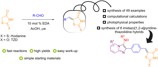
- condensation-type reaction using ethylenediamine (EDA) as catalyst in AcOH under microwave (μw) heating. This convenient methodology is broad in scope, provides the condensation products in high yields (up to 99%), with a reasonable catalyst loading (10 mol %) in only 30 minutes. This approach also enabled the
- -benzylidenethiazol-4-one (3’) in moderate yield (Scheme 1). The implications and scope of this finding will be published in due course. Switching to aromatic (pyridine) or tertiary amines (Et3N) resulted in low yields (Table 1, entries 11 and 12). In contrast, the use of ethylenediamine (EDA) stood out, delivering
- decrease in yields (Table 1, entries 19–21). To confirm the critical role of ethylenediamine in the reaction mechanism, an experiment without its presence was conducted, resulting in only 2% of the desired product (Table 1, entry 22). With the optimized reaction conditions established, this methodology was

Graphical Abstract

Figure 1: Structure of thiazolidinone derivatives.

Figure 2: Selected examples of commercial drugs containing the thiazolidinone core.

Scheme 1: Multicomponent reaction of benzaldehyde, rhodanine, and piperidine in ethanol leading directly to a...
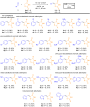
Scheme 2: Substrate scope of the EDA-catalyzed Knoevenagel condensation reactions using a range of aromatic/h...

Scheme 3: Limitations of the EDA-catalyzed Knoevenagel reactions for the synthesis of rhodanine or thiazolidi...

Scheme 4: Plausible reaction mechanism for the EDA-catalyzed Knoevenagel condensation reactions.

Scheme 5: Substrate scope of the HPW-catalyzed GBB reactions.

Scheme 6: Synthesis of imidazo[1,2-a]pyridine-thiazolidinone hybrids by EDA-catalyzed Knoevenagel condensatio...
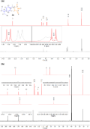
Figure 3: Overlay of predicted (red) and experimental (black) NMR spectra for compound 3n: a) 1H NMR spectra ...

Figure 4: a) Molecular structure of 3n with crystallographic labeling (50% probability displacement). b) Pers...

Scheme 7: a) Tautomeric forms of thiazolidinones and b) resonance structures for compounds 3n and 4n.

Figure 5: Molecular energy as a function of the torsion angle obtained from a relaxed dihedral scan at the M0...

Figure 6: Identification of the carbon atoms used in the theoretical study of chemical shifts. In red, easily...

Figure 7: a) Visual impressions of the solvatochromic study in various solvents (10−5 M) after excitation wit...

Scheme 8: Proposed ICT-type mechanism for the fluorescence process, adapted from ref. [89].

Figure 8: Photophysical study in aqueous solution under different pH values for compound 3n (10−5 M) at room ...

Scheme 9: Two equilibria of compound 3n in aqueous solutions, adapted from ref. [92,93].

Figure 9: Molecular fragments associated with intramolecular charge transfer states.

Figure 10: Frontier molecular orbitals of compounds 3n and 4n in three different states: protonated, deprotona...
Manganese-catalyzed C–C and C–N bond formation with alcohols via borrowing hydrogen or hydrogen auto-transfer
- Mohd Farhan Ansari,
- Atul Kumar Maurya,
- Abhishek Kumar and
- Saravanakumar Elangovan
Beilstein J. Org. Chem. 2024, 20, 1111–1166, doi:10.3762/bjoc.20.98

- polyethyleneimine derivatives by coupling ethylene glycol and ethylenediamine using manganese-pincer catalyst Mn1 (1 mol %), t-BuOK (10 mol %) in toluene at 150 °C (Scheme 21) [48]. The mechanistic investigation based on the experimental and DFT calculations suggested a BH pathway. First, dehydrogenation of the
- ethylene glycol followed by condensation with ethylenediamine generated the corresponding imine intermediates. The subsequent hydrogenation with borrowed hydrogen finally formed the polyethyleneimine product. In 2023, Royo and co-workers conveyed the N-alkylation of amines with alcohols using the bis

Graphical Abstract

Scheme 1: General scheme of the borrowing hydrogen (BH) or hydrogen auto-transfer (HA) methodology.
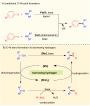
Scheme 2: General scheme for C–N bond formation. A) Traditional cross-couplings with alkyl or aryl halides. B...

Figure 1: Manganese pre-catalysts used for the N-alkylation of amines with alcohols.

Scheme 3: Manganese(I)-pincer complex Mn1 used for the N-alkylation of amines with alcohols and methanol.

Scheme 4: N-Methylation of amines with methanol using Mn2.

Scheme 5: C–N-Bond formation with amines and methanol using PN3P-Mn complex Mn3 reported by Sortais et al. [36]. a...

Scheme 6: Base-assisted synthesis of amines and imines with Mn4. Reaction assisted by A) t-BuOK and B) t-BuON...

Scheme 7: Coupling of alcohols and hydrazine via the HB approach reported by Milstein et al. [38]. aReaction time...

Scheme 8: Proposed mechanism for the coupling of alcohols and hydrazine catalyzed by Mn5.

Scheme 9: Phosphine-free manganese catalyst for N-alkylation of amines with alcohols reported by Balaraman an...

Scheme 10: N-Alkylation of sulfonamides with alcohols.

Scheme 11: Mn–NHC catalyst Mn6 applied for the N-alkylation of amines with alcohols. a3 mol % of Mn6 were used....

Scheme 12: N-Alkylation of amines with primary and secondary alcohols. a80 °C, b100 °C.

Scheme 13: Manganese(III)-porphyrin catalyst for synthesis of tertiary amines.

Scheme 14: Proposed mechanism for the alcohol dehydrogenation with Mn(III)-porphyrin complex Mn7.

Scheme 15: N-Methylation of nitroarenes with methanol using catalyst Mn3.
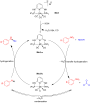
Scheme 16: Mechanism of manganese-catalyzed methylation of nitroarenes using Mn3 as the catalyst.

Scheme 17: Bidentate manganese complex Mn8 applied for the N-alkylation of primary anilines with alcohols. aOn...

Scheme 18: N-Alkylation of amines with alcohols in the presence of manganese salts and triphenylphosphine as t...

Scheme 19: N-Alkylation of diazo compounds with alcohols using catalyst Mn9.

Scheme 20: Proposed mechanism for the amination of alcohols with diazo compounds catalyzed by catalyst Mn9.

Scheme 21: Mn1 complex-catalyzed synthesis of polyethyleneimine from ethylene glycol and ethylenediamine.

Scheme 22: Bis-triazolylidene-manganese complex Mn10 for the N-alkylation of amines with alcohols.

Figure 2: Manganese complexes applied for C-alkylation reactions of ketones with alcohols.

Scheme 23: General scheme for the C–C bond formation with alcohols and ketones.

Scheme 24: Mn1 complex-catalyzed α-alkylation of ketones with primary alcohols.
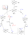
Scheme 25: Mechanism for the Mn1-catalyzed alkylation of ketones with alcohols.

Scheme 26: Phosphine-free in situ-generated manganese catalyst for the α-alkylation of ketones with primary al...
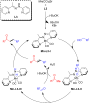
Scheme 27: Plausible mechanism for the Mn-catalyzed α-alkylation of ketones with alcohols.

Scheme 28: α-Alkylation of esters, ketones, and amides using alcohols catalyzed by Mn11.

Scheme 29: Mono- and dialkylation of methylene ketones with primary alcohols using the Mn(acac)2/1,10-phenanth...

Scheme 30: Methylation of ketones with methanol and deuterated methanol.

Scheme 31: Methylation of ketones and esters with methanol. a50 mol % of t-BuOK were used, bCD3OD was used ins...
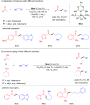
Scheme 32: Alkylation of ketones and secondary alcohols with primary alcohols using Mn4.

Scheme 33: Bidentate manganese-NHC complex Mn6 applied for the synthesis of alkylated ketones using alcohols.

Scheme 34: Mn1-catalyzed synthesis of substituted cycloalkanes by coupling diols and secondary alcohols or ket...
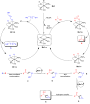
Scheme 35: Proposed mechanism for the synthesis of cycloalkanes via BH method.

Scheme 36: Synthesis of various cycloalkanes from methyl ketones and diols catalyze by Mn13. aReaction time wa...

Scheme 37: N,N-Amine–manganese complex (Mn13)-catalyzed alkylation of ketones with alcohols.

Scheme 38: Naphthyridine‑N‑oxide manganese complex Mn14 applied for the alkylation of ketones with alcohols. a...
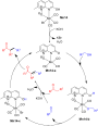
Scheme 39: Proposed mechanism of the naphthyridine‑N‑oxide manganese complex (Mn14)-catalyzed alkylation of ke...

Scheme 40: α-Methylation of ketones and indoles with methanol using Mn15.

Scheme 41: α-Alkylation of ketones with primary alcohols using Mn16. aNMR yield.

Figure 3: Manganese complexes used for coupling of secondary and primary alcohols.
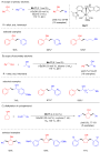
Scheme 42: Alkylation of secondary alcohols with primary alcohols catalyzed by phosphine-free catalyst Mn17. a...

Scheme 43: PNN-Manganese complex Mn18 for the alkylation of secondary alcohols with primary alcohols.
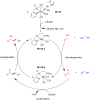
Scheme 44: Mechanism for the Mn-pincer catalyzed C-alkylation of secondary alcohols with primary alcohols.

Scheme 45: Upgrading of ethanol with methanol for isobutanol production.

Scheme 46: Mn-Pincer catalyst Mn19 applied for the β-methylation of alcohols with methanol. a2.0 mol % of Mn19...

Scheme 47: Functionalized ketones from primary and secondary alcohols catalyzed by Mn20. aMn20 (5 mol %), NaOH...
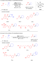
Scheme 48: Synthesis of γ-disubstituted alcohols and β-disubstituted ketones through Mn9-catalyzed coupling of...
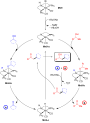
Scheme 49: Proposed mechanism for the Mn9-catalyzed synthesis of γ-disubstituted alcohols and β-disubstituted ...

Scheme 50: Dehydrogenative coupling of ethylene glycol and primary alcohols catalyzed by Mn4.

Scheme 51: Mn18-cataylzed C-alkylation of unactivated esters and amides with alcohols.

Scheme 52: Alkylation of amides and esters using Mn21.

Scheme 53: α-Alkylation of nitriles with primary alcohols using in situ-generated manganese catalyst.

Scheme 54: Proposed mechanism for the α-alkylation of nitriles with primary alcohols.

Scheme 55: Mn9-catalyzed α-alkylation of nitriles with primary alcohols. a1,4-Dioxane was used as solvent, 24 ...

Figure 4: Manganese complexes used for alkylation of heterocyclic compounds.

Scheme 56: Aminomethylation of aromatic compounds with secondary amines and methanol catalyzed by Mn22.
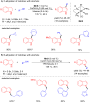
Scheme 57: Regioselective alkylation of indolines with alcohols catalyzed by Mn9. aMn9 (4 mol %), 48 h.

Scheme 58: Proposed mechanism for the C- and N-alkylation of indolines with alcohols.

Scheme 59: C-Alkylation of methyl N-heteroarenes with primary alcohols catalyzed by Mn1. aTime was 60 h.

Scheme 60: C-Alkylation of oxindoles with secondary alcohols.
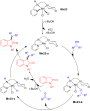
Scheme 61: Plausible mechanism for the Mn23-catalyzed C-alkylation of oxindoles with secondary alcohols.

Scheme 62: Synthesis of C-3-alkylated products by coupling alcohols with indoles and aminoalcohols.

Scheme 63: C3-Alkylation of indoles using Mn1.

Scheme 64: C-Methylation of indoles with Mn15 and methanol.

Scheme 65: α-Alkylation of 2-oxindoles with primary and secondary alcohols catalyzed by Mn25. aReaction carrie...

Scheme 66: Dehydrogenative alkylation of indolines with Mn1. aMn1 (5.0 mol %) was used.

Scheme 67: Synthesis of bis(indolyl)methane derivatives from indoles and alcohols catalyzed by Mn26. aMn26 (5....

Scheme 68: One-pot synthesis of pyrimidines via BH.

Scheme 69: Synthesis of pyrroles from alcohols and aminoalcohols using Mn4.

Scheme 70: Synthesis of pyrroles via multicomponent reaction catalyzed by Mn12.

Scheme 71: Friedländer quinoline synthesis using an in situ-generated phosphine-free manganese catalyst.

Scheme 72: Quinoline synthesis using bis-N-heterocyclic carbene-manganese catalyst Mn6.

Scheme 73: Quinoline synthesis using manganese(III)-porphyrin catalyst Mn7.

Scheme 74: Manganese-catalyzed tetrahydroquinoline synthesis via borrowing BH.

Scheme 75: Proposed mechanism for the manganese-catalyzed tetrahydroquinoline synthesis.

Scheme 76: Synthesis of C3-alkylated indoles using Mn24.

Scheme 77: Synthesis of C-3-alkylated indoles using Mn1.

Scheme 78: C–C Bond formation by coupling of alcohols and ylides.

Scheme 79: C-Alkylation of fluorene with alcohols catalyzed by Mn24.
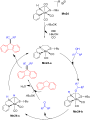
Scheme 80: Proposed mechanism for the C-alkylation of fluorene with alcohols catalyzed by Mn24.

Scheme 81: α-Alkylation of sulfones using Mn-PNN catalyst Mn28.
Green and sustainable approaches for the Friedel–Crafts reaction between aldehydes and indoles
- Periklis X. Kolagkis,
- Eirini M. Galathri and
- Christoforos G. Kokotos
Beilstein J. Org. Chem. 2024, 20, 379–426, doi:10.3762/bjoc.20.36
- research group explored the activity of cadmium sulfide (CdS) nanotubes as heterogeneous nanocatalysts for the electrophilic condensation between aldehydes and indoles [106]. The nanorods were obtained with a solvothermal technique, where thiourea and cadmium nitrate were mixed in ethylenediamine for 10

Graphical Abstract

Scheme 1: Examples of BIMs used for their medicinal properties.

Scheme 2: Mechanisms for the synthesis of BIMs using protic or Lewis acids as catalysts.

Scheme 3: Synthesis of bis(indolyl)methanes using DBDMH.

Scheme 4: Competition experiments and synthesis of bis(indolyl)methanes using DBDMH.

Scheme 5: Proposed mechanism for formation of BIM of using DBDMH.

Scheme 6: Synthesis of bis(indolyl)methanes using I2.

Scheme 7: General reaction mechanism upon halogen bonding.

Scheme 8: Synthesis of bis(indolyl)methanes using I2, introduced by Ji.

Scheme 9: Synthesis of bis(indolyl)methanes using Br2 in CH3CN.

Scheme 10: Βidentate halogen-bond donors.

Scheme 11: Synthesis of bis(indolyl)methanes using bidentate halogen-bond donor 26.

Scheme 12: Proposed reaction mechanism.

Scheme 13: Synthesis of bis(indolyl)methanes using iodoalkyne as catalyst.

Scheme 14: Proposed reaction mechanism.

Scheme 15: Optimized reaction conditions used by Ramshini.

Scheme 16: Activation of the carbonyl group by HPA/TPI-Fe3O4.

Scheme 17: Synthesis of BIMs in the presence of nanoAg-Pt/SiO2-doped silicate.

Scheme 18: Mechanism of action proposed by Khalafi-Nezhad et al.

Scheme 19: Activation of the carbonyl group by the Cu–isatin Schiff base complex.

Scheme 20: Optimum reaction conditions published by Jain.

Scheme 21: Organocatalytic protocol utilizing nanoparticles introduced by Bankar.
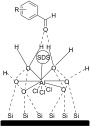
Scheme 22: Activation of the carbonyl group by the AlCl3·6H2O-SDS-SiO2 complex.

Scheme 23: Optimal reaction conditions for the aforementioned nano-Fe3O4 based catalysts.

Scheme 24: Nanocatalytic protocol proposed by Kaur et al.

Scheme 25: Microwave approach introduced by Yuan.

Scheme 26: Microwave approach introduced by Zahran et al.

Scheme 27: Microwave irradiation protocol introduced by Bindu.

Scheme 28: Silica-supported microwave irradiation protocol.

Scheme 29: Proposed mechanism for formation of BIM by Nongkhlaw.

Scheme 30: Microwave-assisted synthesis of BIMs catalyzed by succinic acid.

Scheme 31: Proposed mechanism of action of MMO-4.

Scheme 32: Catalytic approach introduced by Muhammadpoor-Baltork et al.

Scheme 33: Reaction conditions used by Xiao-Ming.

Scheme 34: Ultrasonic irradiation-based protocol published by Saeednia.

Scheme 35: Pyruvic acid-mediated synthesis of BIMs proposed by Thopate.

Scheme 36: Synthesis of BIMs using [bmim]BF4 or [bmim]PF6 ionic liquids.

Scheme 37: Synthesis of BIMs utilizing In(OTf)3 in octylmethylimidazolium hexafluorophosphate as ionic liquid.

Scheme 38: FeCl3·6H2O-catalyzed synthesis of BIMs with use of ionic liquid.

Scheme 39: Synthesis of BIMs utilizing the [hmim]HSO4/EtOH catalytic system.

Scheme 40: Synthesis of BIMs utilizing acidic ionic liquid immobilized on silica gel (ILIS-SO2Cl).

Scheme 41: The [bmim][MeSO4]-catalyzed reaction of indole with various aldehydes.

Scheme 42: The role of [bmim][MeSO4] in catalyzing the reaction of indole with aldehydes.

Scheme 43: Synthesis of BIMs utilizing FeCl3-based ionic liquid ([BTBAC]Cl-FeCl3) as catalyst.

Scheme 44: Synthesis of BIMs using [Msim]Cl at room temperature.

Scheme 45: [Et3NH][H2PO4]-catalyzed synthesis of bis(indolyl)methanes.

Scheme 46: PILs-catalyzed synthesis of bis(indolyl)methanes.

Scheme 47: FSILs-mediated synthesis of bis(indolyl)methanes.

Scheme 48: Possible “release and catch” catalytic process.

Scheme 49: Synthesis of bis(indolyl)methanes by [DABCO-H][HSO4].

Scheme 50: Synthesis of bis(indolyl)methanes by [(THA)(SO4)].

Scheme 51: Synthesis of BBSI-Cl and BBSI-HSO4.

Scheme 52: Synthesis of BIMs in the presence of BBSI-Cl and BBSI-HSO4.

Scheme 53: Chemoselectivity of the present method.

Scheme 54: Synthesis of BIMs catalyzed by chitosan-supported ionic liquid.

Scheme 55: Proposed mechanism of action of CSIL.

Scheme 56: Optimization of the reaction in DESs.

Scheme 57: Synthesis of BIMs using ChCl/SnCl2 as DES.

Scheme 58: Synthesis of BIMs derivatives in presence of DES.

Scheme 59: BIMs synthesis in choline chloride/urea (CC/U).

Scheme 60: Flow chemistry-based synthesis of BIMs by Ley.

Scheme 61: Flow chemistry-based synthesis of BIMs proposed by Nam et al.

Scheme 62: Amino-catalyzed reaction of indole with propionaldehyde.

Scheme 63: Aminocatalytic synthesis of BIMs.

Scheme 64: Proposed mechanism for the aminocatalytic synthesis of BIMs.

Scheme 65: Enzymatic reaction of indole with aldehydes.

Scheme 66: Proposed mechanism for the synthesis of BIMs catalyzed by TLIM.

Scheme 67: Proposed reaction mechanism by Badsara.

Scheme 68: Mechanism proposed by D’Auria.

Scheme 69: Photoinduced thiourea catalysis.

Scheme 70: Proposed mechanism of photoacid activation.

Scheme 71: Proposed mechanism of action for CF3SO2Na.

Scheme 72: Proposed mechanism for the synthesis of BIMs by Mandawad.

Scheme 73: Proposed mechanism for the (a) acid generation and (b) synthesis of BIMs.

Scheme 74: a) Reaction conditions employed by Khaksar and b) activation of the carbonyl group by HFIP.

Scheme 75: Activation of the carbonyl group by the PPy@CH2Br through the formation of a halogen bond.

Scheme 76: Reaction conditions utilized by Mhaldar et al.

Scheme 77: a) Reaction conditions employed by López and b) activation of the carbonyl group by thiourea.

Scheme 78: Infrared irradiation approach introduced by Luna-Mora and his research group.

Scheme 79: Synthesis of BIMs with the use of the Fe–Zn BMOF.
Active-metal template clipping synthesis of novel [2]rotaxanes
- Cătălin C. Anghel,
- Teodor A. Cucuiet,
- Niculina D. Hădade and
- Ion Grosu
Beilstein J. Org. Chem. 2023, 19, 1776–1784, doi:10.3762/bjoc.19.130
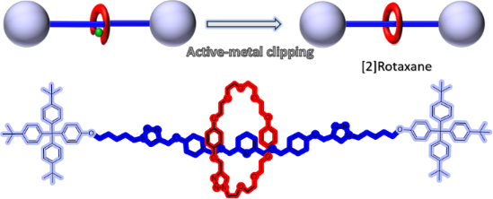
- equiv) dissolved in MeCN (5 mL) were added dropwise during 12 hours by using a push-syringe. The mixture was stirred for 48 hours at room temperature. The solvent was evaporated and the residue was dissolved in DCM (25 mL), followed by washings with N-(2-hydroxyethyl)ethylenediamine-N,N′,N′-triacetic

Graphical Abstract

Figure 1: a. Active-metal template (reported in the literature) and b. active-metal template clipping (used i...

Figure 2: Macrocyclic components of the [2]rotaxanes.

Scheme 1: Synthesis of the key intermediates 6 and 8 and of the reference macrocycle M1.

Scheme 2: Synthesis of [2]rotaxanes R1 and R2.

Figure 3: Top: HRESI(+)-MS spectrum of the rotaxane R1 (left) and R2 (right) [experimental (top) and calculat...
Synthesis of ether lipids: natural compounds and analogues
- Marco Antônio G. B. Gomes,
- Alicia Bauduin,
- Chloé Le Roux,
- Romain Fouinneteau,
- Wilfried Berthe,
- Mathieu Berchel,
- Hélène Couthon and
- Paul-Alain Jaffrès
Beilstein J. Org. Chem. 2023, 19, 1299–1369, doi:10.3762/bjoc.19.96
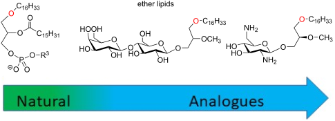

Graphical Abstract

Figure 1: Chemical structure of some natural ether lipids (ELs).

Figure 2: Synthesis of lyso-PAF and PAF from 1-O-alkylglycerol [64].

Figure 3: Synthesis of lyso-PAF from 1,3-benzylideneglycerol 3.1 [69].
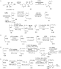
Figure 4: A) Synthesis of the two enantiomers of octadecylglycerol (4.6 and 4.10) from ᴅ-mannitol (4.1); B) s...

Figure 5: Four-step synthesis of PAF 5.6 from (S)-glycidol [73].

Figure 6: Synthesis of 1-O-alkylglycerol A) from solketal, B) from ᴅ- or ʟ-tartaric acid and the intermediate ...

Figure 7: Synthesis of EL building blocks starting from substituted glycidol 7.1a–c [82].

Figure 8: Synthesis of PAF 8.5 by using phosphoramidite 8.2 [86].

Figure 9: Synthesis of oleyl-PAF 9.7 from ʟ-serine [88].

Figure 10: Synthesis of racemic analogues of lyso-PAF 10.8 and PAF 10.9 featuring a phenyl group between the g...

Figure 11: Synthesis of racemic deoxy-lyso-PAF 11.7 and deoxy-PAF 11.8 [91].

Figure 12: Synthesis of racemic thio-PAF 12.8 [93].

Figure 13: Racemic synthesis of 13.6 to illustrate the modification of the glycerol backbone by adding a methy...

Figure 14: Racemic synthesis of 14.5 as an illustration of the introduction of methyl substituents on the glyc...

Figure 15: Synthesis of functionalized sn-2-acyl chains of PC-EL; A) Steglich esterification or acylation reac...

Figure 16: Synthesis of racemic mc-PAF (16.3), a carbamate analogue of PAF [102].

Figure 17: A) Synthesis of (R)-17.2 and (S)-17.6 starting from (S)-solketal (17.1); B) synthesis of N3-PAF (17...

Figure 18: Modification of the phosphocholine polar head to produce PAF analogues [81].

Figure 19: Racemic PAF analogues 19.3 and 19.5 characterized by the absence of the phosphate group [107].

Figure 20: Synthesis of PIP3-PAF (20.7) [108].

Figure 21: Large-scale synthesis of C18-edelfosine (21.8) [116].

Figure 22: Synthesis of C16-edelfosine (22.10) starting from isopropylidene-ʟ-glyceric acid methyl ester (22.1...

Figure 23: Phosphocholine moiety installation by the use of chlorophosphite 23.2 as key reagent [119].

Figure 24: Synthesis of rac-1-alkyl-2-O-methylglycerol (AMG) [120].

Figure 25: Synthesis of stereocontrolled 1-alkyl-2-O-methyl glycerol 25.9 (AMG) from dimethyl ᴅ-tartrate [81].

Figure 26: A) Racemic synthesis of thioether 26.4 [129,130], B) structure of sulfone analogue 26.5 [129].

Figure 27: Stereocontrolled synthesis of C18-edelfosine thioether analogue 27.8 [118].

Figure 28: Synthesis of thioether 28.4 that include a thiophosphate function [134].

Figure 29: Synthesis of ammonium thioether 29.4 and 29.6 [135].

Figure 30: Synthesis of the N-methylamino analogue of edelfosine 30.6 (BN52211) [138].

Figure 31: Synthesis of 1-desoxy analogues of edelfosine; A) with a saturated alkyl chain; B) synthesis of the...

Figure 32: Stereocontrolled synthesis of edelfosine analogue (S)-32.8 featuring a C18:1 lipid chain [142].

Figure 33: Synthesis of edelfosine analogues with modulation of the lipid chain; A) illustration with the synt...

Figure 34: Synthesis of phospholipid featuring a carbamate function to link the lipid chain to the glycerol un...

Figure 35: Synthesis of sesquiterpene conjugates of phospho glycero ether lipids [148].

Figure 36: Racemic synthesis of methyl-substituted glycerol analogues 36.7 and 36.10: A) synthesis of diether ...

Figure 37: Racemic synthesis of ilmofosine (37.6) [155,156].

Figure 38: A) Stereoselective synthesis of 38.5 via a stereoselective hydroboration reaction; B) synthesis of ...

Figure 39: Racemic synthesis of SRI62-834 (39.6) featuring a spiro-tetrahydrofurane heterocycle in position 2 ...

Figure 40: Racemic synthesis of edelfosine analogue 40.5 featuring an imidazole moiety in sn-2 position [160].

Figure 41: Racemic synthesis of fluorine-functionalized EL: A) Synthesis of 41.6 and B) synthesis of 41.8 [161-163].

Figure 42: A) Synthesis of the β-keto-ester 42.6 that also features a decyl linker between the phosphate and t...

Figure 43: Synthesis of phosphonate-based ether lipids; A) edelfosine phosphonate analogue 43.7 and B) thioeth...

Figure 44: Enantioselective synthesis of phosphonates 44.3 and 44.4 [171].

Figure 45: Racemic synthesis of phosphinate-based ether lipid 45.10 [172].

Figure 46: Racemic synthesis of edelfosine arsonium analogue 46.5 [173].

Figure 47: Synthesis of edelfosine dimethylammonium analogue 47.2 [118].

Figure 48: Synthesis of rac-C18-edelfosine methylammonium analogue 48.4 [176].

Figure 49: A) Synthesis of edelfosine N-methylpyrrolidinium analogue 49.2 or N-methylmorpholinium analogue 49.3...

Figure 50: A) Synthesis of edelfosine’s analogue 50.4 with a PE polar group; B) illustration of a pyridinium d...

Figure 51: A) Synthesis of 51.4 featuring a thiazolium cationic moiety; B) synthesis of thiazolium-based EL 51...

Figure 52: Synthesis of cationic ether lipids 52.3, 52.4 and 52.6 [135,183].

Figure 53: Synthesis of cationic carbamate ether lipid 53.5 [184].

Figure 54: Synthesis of cationic sulfonamide 54.5 [185].

Figure 55: Chemical structure of ONO-6240 (55.1) and SRI-63-119 (55.2).

Figure 56: Synthesis of non-ionic ether lipids 56.2–56.9 [188].

Figure 57: Synthesis of ether lipid conjugated to foscarnet 57.6 [189].

Figure 58: A) Synthesis of ether lipid conjugated to arabinofuranosylcytosine; B) synthesis of AZT conjugated ...

Figure 59: Synthesis of quercetin conjugate to edelfosine [191].

Figure 60: Synthesis of 60.8 (Glc-PAF) [194].

Figure 61: A) Synthesis of amino ether lipid 61.7 functionalized with a rhamnose unit and its amide analogue 6...

Figure 62: A) Synthesis of glucose ether lipid 62.4; B) structure of ether lipid 62.5 possessing a maltose uni...

Figure 63: A) Synthesis of glucuronic methyl ester 63.8; B) structure of cellobiose 63.9 and maltose 63.10 ana...

Figure 64: A) Synthesis of maltosyl glycerolipid 64.7; B) structure of lactose analogue 64.8 prepared followin...

Figure 65: A) Asymmetric synthesis of the aglycone moiety starting from allyl 4-methoxyphenyl ether; B) glycos...

Figure 66: A) Synthesis of ohmline possessing a lactose moiety. B) Structure of other glyco glycero lipids pre...

Figure 67: A) Synthesis of lactose-glycerol ether lipid 67.5; B) analogues possessing a maltose (67.6) or meli...

Figure 68: Synthesis of digalactosyl EL 68.6, A) by using trityl, benzyl and acetyl protecting groups, B) by u...

Figure 69: A) Synthesis of α-ohmline; B) structure of disaccharide ether lipids prepared by using similar meth...

Figure 70: Synthesis of lactose ether lipid 70.3 and its analogue 70.6 featuring a carbamate function as linke...

Figure 71: Synthesis of rhamnopyranoside diether 71.4 [196].

Figure 72: Synthesis of 1-O-hexadecyl-2-O-methyl-3-S-(α-ᴅ-1'-thioglucopyranosyl)-sn-glycerol (72.5) [225].

Figure 73: A) Preparation of lipid intermediate 73.4; B) synthesis of 2-desoxy-C-glycoside 73.10 [226].

Figure 74: Synthesis of galactose-pyridinium salt 74.3 [228].

Figure 75: Synthesis of myo-inositol derivative Ino-C2-PAF (75.10) [230].

Figure 76: A) Synthesis of myo-inositol phosphate building block 76.7; B) synthesis of myo-inositolphosphate d...

Figure 77: A) Synthesis of phosphatidyl-3-desoxy-inositol 77.4; B) synthesis of phosphono-3-desoxyinositol 77.9...

Figure 78: A) Structure of diether phosphatidyl-myo-inositol-3,4-diphosphate 78.1; B) synthesis of phosphatidy...

Figure 79: A) Synthesis of diether-phosphatidyl derivative 79.4 featuring a hydroxymethyl group in place of a ...

Figure 80: Synthesis of Glc-amine-PAF [78].

Figure 81: Synthesis of glucosamine ether lipid 81.4 and its analogues functionalized in position 3 of the ami...

Figure 82: Synthesis of fully deprotected aminoglucoside ether lipid 82.5 [246].

Figure 83: Synthesis of C-aminoglycoside 83.12 using Ramberg–Bäcklund rearrangement as a key step [250].

Figure 84: A) List of the most important glyco lipids and amino glyco lipids included in the study of Arthur a...

Figure 85: Synthesis of mannosamine ether lipid 85.6 [254].
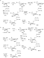
Figure 86: A) Synthesis of glucosamine ether lipids with a non-natural ʟ-glucosamine moiety; B) synthesis of e...
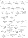
Figure 87: A) Structure of the most efficient anticancer agents 87.1–87.4 featuring a diamino glyco ether lipi...

Figure 88: A) Synthesis of diamino glyco ether lipid 87.4; B) synthesis of bis-glycosylated ether lipid 88.10 [256]....

Figure 89: Synthesis of triamino ether lipid 89.4 [260].

Figure 90: Synthesis of chlorambucil conjugate 90.7 [261].

Figure 91: Three main methods for the preparation of glycerol ether lipid 91.3; A) from solketal and via a tri...

Figure 92: Four different methods for the installation of the phosphocholine polar head group; A) method using...

Figure 93: Illustration of two methods for the installation of saccharides or aminosaccharides; A) O-glycosyla...
Strategies in the synthesis of dibenzo[b,f]heteropines
- David I. H. Maier,
- Barend C. B. Bezuidenhoudt and
- Charlene Marais
Beilstein J. Org. Chem. 2023, 19, 700–718, doi:10.3762/bjoc.19.51
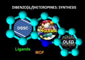
- nitrotoluene (22) under alkaline conditions (e.g., O2, KOt-Bu; O2, KOH, MeOH, ethylenediamine, etc.), as reported by Stansbury and Proops [33]. Aerobic oxidation of 22 in alkaline methanol with added ethylenediamine, gave 21 in 36% yield (Scheme 2), which is poor compared to that reported for the p-nitro

Graphical Abstract

Figure 1: Dibenzo[b,f]azepine (1a), -oxepine (1b) and -thiepine (1c) as examples of dibenzo[b,f]heteropines (1...

Figure 2: Selected pharmaceuticals with the dibenzo[b,f]azepine skeleton.

Figure 3: Examples of 10,11-dihydrodibenzo[b,f]azepine-based ligands.

Figure 4: The dibenzo[b,f]azepine moiety in dyes with properties suitable for the use in organic light emitti...

Figure 5: Selective bioactive natural products (13–18) containing the dibenzo[b,f]oxepine scaffold and Novart...

Scheme 1: Retrosynthetic approach to 5H-dibenzo[b,f]azepine (1a) from nitrotoluene (22).

Scheme 2: Oxidative coupling of o-nitrotoluene (22) and reduction of 2,2'-dinitrobibenzyl (21) to form 2,2'-d...

Scheme 3: Synthesis of 10,11-dihydro-5H-dibenzo[b,f]azepine (2a) via amine condensation.

Scheme 4: Catalytic reduction of 10,11-dihydro-5H-dibenzo[b,f]azepine (2a).

Scheme 5: The Wagner–Meerwein rearrangement of acridin-9-ylmethanol (23) into 5H-dibenzo[b,f]azepine (1a).

Scheme 6: Oxidative ring expansion of 2-(9-xanthenyl)malonates 24.

Scheme 7: Ring expansion via C–H functionalisation.

Scheme 8: The synthesis of fluorinated 5H-dibenzo[b,f]azepine 38 from isatin (32).

Scheme 9: The synthesis of substituted dibenzo[b,f]azepines 43 from indoles 39.

Scheme 10: Retrosynthetic pathways to dibenzo[b,f]azepines via Buchwald–Hartwig amination.

Scheme 11: Synthesis of dibenzo[b,f]oxepine 54 and -azepine 55 derivatives via (i) Heck reaction and (ii) Buch...

Scheme 12: Double Buchwald–Hartwig amination and thioetherification in the synthesis of tricyclic azepines 60 ...

Scheme 13: Double Buchwald–Hartwig amination towards substituted dibenzoazepines 62.

Scheme 14: Double Buchwald–Hartwig amination towards 10,11-dihydro-5H-dibenzo[b,f]azepine derivatives 71.

Scheme 15: One-pot Suzuki coupling–Buchwald–Hartwig amination.

Scheme 16: One-pot Rh/Pd-catalysed synthesis of dihydropyridobenzazepines.

Scheme 17: A retrosynthetic pathway to dibenzo[b,f]azepines via Mizoroki–Heck reaction.

Scheme 18: One-pot domino Pd-catalyzed Mizoroki–Heck–Buchwald–Hartwig synthesis of dibenzo[b,f]azepines.

Scheme 19: Dibenzo[b,f]thiapine and -oxepine synthesis via SNAr (thio)etherification, Wittig methylenation and...

Scheme 20: A retrosynthetic pathway to dibenzo[b,f]oxepines via Ullmann coupling.

Scheme 21: Ullmann-type coupling in dibenzo[b,f]oxepine synthesis.

Scheme 22: Wittig reaction and Ullmann coupling as key steps in dihydrobenz[b,f]oxepine synthesis.

Scheme 23: Pd-catalysed dibenzo[b,f]azepine synthesis via norbornene azepine intermediate 109.

Scheme 24: A simple representation of olefin metathesis resulting in transalkylidenation.

Scheme 25: Ring-closing metathesis as key step in the synthesis of dibenzo[b,f]heteropines.

Scheme 26: Alkyne–aldehyde metathesis in the synthesis of dibenzo[b,f]heteropines.

Scheme 27: Hydroarylation of 9-(2-alkynylphenyl)-9H-carbazole derivatives.

Scheme 28: Oxidative coupling of bisphonium ylide intermediate to give pacharin (13).

Scheme 29: Preparation of 10,11-dihydrodibenzo[b,f]heteropines via intramolecular Wurtz reaction.

Scheme 30: Phenol deprotonation and intramolecular etherification in the synthesis of bauhinoxepine J.

Figure 6: Functionalisation of dibenzo[b,f]azepine.

Scheme 31: Palladium-catalysed N-arylation of dibenzo[b,f]azepine.

Scheme 32: Cu- and Ni-catalysed N-arylation.

Scheme 33: N-Alkylation of dibenzo[b,f]azepine (1a) and dihydrodibenzo[b,f]azepine (2a).

Scheme 34: Preparation of methoxyiminosilbene.

Scheme 35: Synthesis of oxcarbazepine (153) from methoxy iminostilbene 151.

Scheme 36: Ring functionalisation of dihydrodibenzo[b,f]azepine.
Mechanochemical synthesis of unsymmetrical salens for the preparation of Co–salen complexes and their evaluation as catalysts for the synthesis of α-aryloxy alcohols via asymmetric phenolic kinetic resolution of terminal epoxides
- Shengli Zuo,
- Shuxiang Zheng,
- Jianjun Liu and
- Ang Zuo
Beilstein J. Org. Chem. 2022, 18, 1416–1423, doi:10.3762/bjoc.18.147
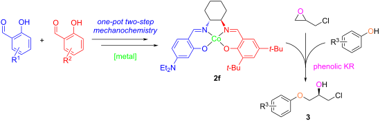
- ethylenediamine monohydrochlorides were grinded with a half equivalent of 4-diethylamino (Et2N‒), 3,5-dichloro (Cl‒), or 3,5-di-tert-butyl (t-Bu‒) salicylaldehydes (blue moieties in Scheme 2) for 10 minutes. The synthesis of diamine monohydrochlorides and characterization data of mono-imine ammonium salts were

Graphical Abstract

Figure 1: Representative asymmetric Co–salen catalysts.

Scheme 1: Synthetic approach to our unsymmetrical Co–salen catalyst 2f for the asymmetric synthesis of α-aryl...

Scheme 2: Mechanochemical one-pot two-step synthesis of unsymmetrical salens 1a–h. Reaction conditions: salic...

Scheme 3: Synthesis of unsymmetrical metal–salen complexes 2. Reaction conditions a: metal acetate hydrate (1...
Synthetic strategies toward 1,3-oxathiolane nucleoside analogues
- Umesh P. Aher,
- Dhananjai Srivastava,
- Girij P. Singh and
- Jayashree B. S
Beilstein J. Org. Chem. 2021, 17, 2680–2715, doi:10.3762/bjoc.17.182
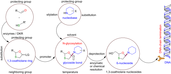
- recrystallized to obtain the enantiomerically pure ʟ-menthyl ester 35a (Scheme 8). Milton et al. [47] synthesized the key intermediate 38 by two synthetic routes. The first route involves a reaction of bromoacetaldehyde diethyl acetal (36) with a xanthate ester, followed by treatment of ethylenediamine, which

Graphical Abstract

Figure 1: Representative modified 1,3-oxathiolane nucleoside analogues.

Figure 2: Mechanism of antiviral action of 1,3-oxathiolane nucleosides, 3TC (1) and FTC (2), as chain termina...

Figure 3: Synthetic strategies for the construction of the 1,3-oxathiolane sugar ring.

Scheme 1: Synthesis of 4 from benzoyloxyacetaldehyde (3a) and 2-mercapto-substituted dimethyl acetal 3na.

Scheme 2: Synthesis of 8 from protected glycolic aldehyde 3b and 2-mercaptoacetic acid (3o).

Scheme 3: Synthesis of 20 from ᴅ-mannose (3c).

Scheme 4: Synthesis of 20 from 1,6-thioanhydro-ᴅ-galactose (3d).

Scheme 5: Synthesis of 8 from 2-(tert-butyldiphenylsilyloxy)methyl-5-oxo-1,2-oxathiolane (3m).

Scheme 6: Synthesis of 20a from ʟ-gulose derivative 3f.

Scheme 7: Synthesis of 31 from (+)-thiolactic acid 3p and 2-benzoyloxyacetaldehyde (3a).

Scheme 8: Synthesis of 35a from 1,4-dithiane-2,5-diol (3q) and glyoxylic acid (3g) hydrate.

Scheme 9: Synthetic routes toward 41 through Pummerer reaction from methyl 2-mercaptoacetate (3j) and bromoac...

Scheme 10: Strategy for the synthesis of 2,5-substituted 1,3-oxathiolane 41a using 4-nitrobenzyl glyoxylate an...

Scheme 11: Synthesis of 44 by a resolution method using Mucor miehei lipase.

Scheme 12: Synthesis of 45 from benzoyloxyacetaldehyde (3a) and 2-mercaptoacetaldehyde bis(2-methoxyethyl) ace...

Scheme 13: Synthesis of 46 from 2-mercaptoacetaldehyde bis(2-methoxyethyl) acetal (3nc) and diethyl 3-phosphon...

Scheme 14: Synthesis of 48 from 1,3-dihydroxyacetone dimer 3l.

Scheme 15: Approach toward 52 from protected alkene 3rb and lactic acid derivative 51 developed by Snead et al....

Scheme 16: Recent approach toward 56a developed by Kashinath et al.

Scheme 17: Synthesis of 56a from ʟ-menthyl glyoxylate (3h) hydrate by DKR.
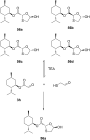
Scheme 18: Possible mechanism with catalytic TEA for rapid interconversion of isomers.

Scheme 19: Synthesis of 35a by a classical resolution method through norephedrine salt 58 formation.

Scheme 20: Synthesis of 63 via [1,2]-Brook rearrangement from silyl glyoxylate 61 and thiol 3nb.

Scheme 21: Combined use of STS and CAL-B as catalysts to synthesize an enantiopure oxathiolane precursor 65.

Scheme 22: Synthesis of 1 and 1a from glycolaldehyde dimer 64 and 1,4-dithiane-2,5-diol (3q) using STS and CAL...

Scheme 23: Synthesis of 68 by using Klebsiella oxytoca.

Scheme 24: Synthesis of 71 and 72 using Trichosporon taibachii lipase and kinetic resolution.

Scheme 25: Synthesis of 1,3-oxathiolan-5-ones 77 and 78 via dynamic covalent kinetic resolution.

Figure 4: Pathway for glycosidic bond formation.

Scheme 26: First synthesis of (±)-BCH-189 (1c) by Belleau et al.

Scheme 27: Enantioselective synthesis of 3TC (1).

Scheme 28: Synthesis of cis-diastereomer 3TC (1) from oxathiolane propionate 44.

Scheme 29: Synthesis of (±)-BCH-189 (1c) via SnCl4-mediated N-glycosylation of 8.

Scheme 30: Synthesis of (+)-BCH-189 (1a) via TMSOTf-mediated N-glycosylation of 20.

Scheme 31: Synthesis of 3TC (1) from oxathiolane precursor 20a.

Scheme 32: Synthesis of 83 via N-glycosylation of 20 with pyrimidine bases.

Scheme 33: Synthesis of 85 via N-glycosylation of 20 with purine bases.

Scheme 34: Synthesis of 86 and 87 via N-glycosylation using TMSOTf and pyrimidines.

Scheme 35: Synthesis of 90 and 91 via N-glycosylation using TMSOTf and purines.

Scheme 36: Synthesis of 3TC (1) via TMSI-mediated N-glycosylation.

Scheme 37: Stereoselective N-glycosylation for the synthesis of 1 by anchimeric assistance of a chiral auxilia...

Scheme 38: Whitehead and co-workers’ approach for the synthesis of 1 via direct N-glycosylation without an act...

Scheme 39: ZrCl4-mediated stereoselective N-glycosylation.

Scheme 40: Plausible reaction mechanism for stereoselective N-glycosylation using ZrCl4.

Scheme 41: Synthesis of enantiomerically pure oxathiolane nucleosides 1 and 2.

Scheme 42: Synthesis of tetrazole analogues of 1,3-oxathiolane nucleosides 97.

Scheme 43: Synthetic approach toward 99 from 1,3-oxathiolane 45 by Camplo et al.
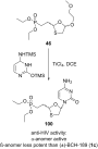
Scheme 44: Synthesis of 100 from oxathiolane phosphonate analogue 46.

Scheme 45: Synthetic approach toward 102 and the corresponding cyclic thianucleoside monophosphate 102a by Cha...

Scheme 46: Synthesis of emtricitabine (2) from 1,4-dithiane-2,5-diol (3q) and glyoxylic acid (3g).

Scheme 47: Synthesis of 1 and 2, respectively, from 56a–d using iodine-mediated N-glycosylation.
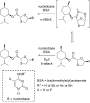
Scheme 48: Plausible mechanism for silane- and I2-mediated N-glycosylation.

Scheme 49: Pyridinium triflate-mediated N-glycosylation of 35a.

Scheme 50: Possible pathway for stereoselective N-glycosylation via in situ chelation with a metal ligand.

Scheme 51: Synthesis of novel 1,3-oxathiolane nucleoside 108 from oxathiolane precursor 8 and 3-benzyloxy-2-me...

Scheme 52: Synthesis of 110 using T-705 as a nucleobase and 1,3-oxathiolane derivative 8 via N-glycosylation.

Scheme 53: Synthesis of 1 using an asymmetric leaving group and N-glycosylation with bromine and mesitylene.

Scheme 54: Cytidine deaminase for enzymatic separation of 1c.

Scheme 55: Enzymatic resolution of the monophosphate derivative 116 for the synthesis of (−)-BCH-189 (1) and (...

Scheme 56: Enantioselective resolution by PLE-mediated hydrolysis to obtain FTC (2).

Scheme 57: (+)-Menthyl chloroformate as a resolving agent to separate a racemic mixture 120.

Scheme 58: Separation of racemic mixture 1c by cocrystal 123 formation with (S)-(−)-BINOL.
Cationic oligonucleotide derivatives and conjugates: A favorable approach for enhanced DNA and RNA targeting oligonucleotides
- Mathias B. Danielsen and
- Jesper Wengel
Beilstein J. Org. Chem. 2021, 17, 1828–1848, doi:10.3762/bjoc.17.125
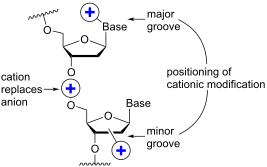
- significant improvement in Tm was observed when the functionalizing groups were changed from ethylenediamine to either trimethylenediamine (monomer 42) or putrescine (monomer 43), demonstrating that the length between the cationic amino group and the sugar scaffold is important for the thermal stability
- 74) (DMAP) [107], and the other the N,N-diethyl-ethylenediamine phosphoramidate linkage (75) (DEED) [108]. Stereo-uniform ONs (either Rp or Sp) containing the DMAP modification were synthesized via dinucleotide derivatives obtained by a phosphitylation reaction followed by oxidative amidate coupling

Graphical Abstract

Figure 1: A schematic representation of 16-mer ASOs in different designs. White circles represent unmodified ...

Figure 2: Structures of 5-(1-propargylamino)-2’-deoxyuridine (A) and 2’-aminoethoxy-5-propargylaminouridine (...
Chemical approaches to discover the full potential of peptide nucleic acids in biomedical applications
- Nikita Brodyagin,
- Martins Katkevics,
- Venubabu Kotikam,
- Christopher A. Ryan and
- Eriks Rozners
Beilstein J. Org. Chem. 2021, 17, 1641–1688, doi:10.3762/bjoc.17.116
- –dsRNA triplexes [74]. γ-Modified PNA: Later studies focused on introducing substituents in the ethylenediamine moiety of the PNA backbone. Ly and co-workers showed that introduction of simple substituents, such as methyl (derived from ʟ-alanine) or hydroxymethyl (derived from ʟ-serine) at the γ-position

Graphical Abstract

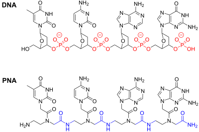
Figure 1: Structure of DNA and PNA.

Figure 2: PNA binding modes: (A) PNA–dsDNA 1:1 triplex; (B) PNA–DNA–PNA strand-invasion triplex; (C) the Hoog...

Figure 3: Structure of P-form PNA–DNA–PNA triplex from reference [41]. (A) view in the major groove and (B) view ...

Figure 4: Structures of backbone-modified PNA.

Figure 5: Structures of PNA having α- and γ-substituted backbones.

Figure 6: Structures of modified nucleobases in PNA to improve Hoogsteen hydrogen bonding to guanine and aden...

Figure 7: Proposed hydrogen bonding schemes for modified PNA nucleobases designed to recognize pyrimidines or...

Figure 8: Modified nucleobases to modulate Watson–Crick base pairing and chemically reactive crosslinking PNA...

Figure 9: Examples of triplets formed by Janus-wedge PNA nucleobases (blue). R1 denotes DNA, RNA, or PNA back...

Figure 10: Examples of fluorescent PNA nucleobases. R1 denotes DNA, RNA, or PNA backbones.

Figure 11: Endosomal entrapment and escape pathways of PNA and PNA conjugates.
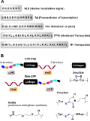
Figure 12: (A) representative cell-penetrating peptides (CPPs), (B) conjugation designs and linker chemistries....

Figure 13: Proposed delivery mode by pHLIP-PNA conjugates (A) the transmembrane section of pHLIP interacting w...

Figure 14: Structures of modified penetratin CPP conjugates with PNA linked through either disulfide (for stud...

Figure 15: Chemical structure of C9–PNA, a stable amphipathic (cyclic-peptide)–PNA conjugate.
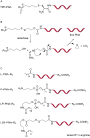
Figure 16: Structures of PNA conjugates with a lipophilic triphenylphosphonium cation (TPP–PNA) through (A) th...

Figure 17: Structures of (A) chloesteryl–PNA, (B) cholate–PNA and (C) cholate–PNA(cholate)3.
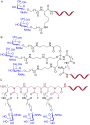
Figure 18: Structures of PNA–GalNAc conjugates (A) (GalNAc)2K, (B) triantennary (GalNAc)3, and (C) trivalent (...
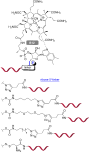
Figure 19: Vitamin B12–PNA conjugates with different linkages.

Figure 20: Structures of (A) neomycin B, (B) PNA–neamine conjugate, and (C) PNA–neosamine conjugate.

Figure 21: PNA clamp (red) binding to target DNA containing a mixture of sequences (A) PNA binds with higher a...

Figure 22: Rolling circle amplification using PNA openers (red) to invade a dsDNA target forming a P-loop. A p...

Figure 23: Molecular beacons containing generic fluorophores (Fl) and quenchers (Q) recognizing a complementar...
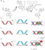
Figure 24: (A) Light-up fluorophores such as thiazole orange display fluorescence enhancement upon binding to ...

Figure 25: Templated fluorogenic detection of oligonucleotides using two PNAs. (A) Templated FRET depends on h...

Figure 26: Lateral flow devices use a streptavidin labeled strip on nitrocellulose paper to anchor a capture P...
Valorisation of plastic waste via metal-catalysed depolymerisation
- Francesca Liguori,
- Carmen Moreno-Marrodán and
- Pierluigi Barbaro
Beilstein J. Org. Chem. 2021, 17, 589–621, doi:10.3762/bjoc.17.53
- (DEG), dipropylene glycol (DPG)) aminolysis (2-aminoethanol, 3-amino-1-propanol, ethylenediamine). Advantages of catalytic processes are obvious and can be witnessed in the hydrolysis and the glycolysis reactions of poly(ethylene terephthalate) (PET) [82][83]. Representative data are reported in

Graphical Abstract

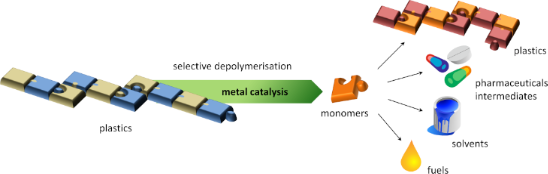
Figure 1: Potential classification of plastic recycling processes. The area covered by the present review is ...

Figure 2: EG produced during glycolytic depolymerisation of PET using DEG + DPG as solvent and titanium(IV) n...

Scheme 1: Simplified representation of the conversion of 1,4-PBD to C16–C44 macrocycles using Ru metathesis c...
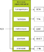
Figure 3: Main added-value monomers obtainable by catalytic depolymerisation of PET via chemolytic methods.

Scheme 2: Hydrogenolytic depolymerisation of PET by ruthenium complexes.

Scheme 3: Depolymerisation of PET via catalytic hydrosilylation by Ir(III) pincer complex.

Scheme 4: Catalytic hydrolysis (top) and methanolysis (bottom) reactions of PET.

Scheme 5: Depolymerisation of PET by glycolysis with ethylene glycol.

Figure 4: Glycolysis of PET: evolution of BHET yield over time, with and without zinc acetate catalyst (196 °...

Scheme 6: Potential activated complex for the glycolysis reaction of PET catalysed by metallated ILs and evol...

Scheme 7: One-pot, two-step process for PET repurposing via chemical recycling.
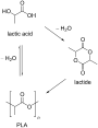
Scheme 8: Synthetic routes to PLA.

Scheme 9: Structures of the zinc molecular catalysts used for PLA-methanolysis in various works. a) See [265], b) ...

Scheme 10: Depolymerisation of PLLA by Zn–N-heterocyclic carbene complex.

Scheme 11: Salalen ligands.

Scheme 12: Catalytic hydrogenolysis of PLA.

Scheme 13: Catalytic hydrosilylation of PLA.

Scheme 14: Hydrogenative depolymerisation of PBT and PCL by molecular Ru catalysts.

Scheme 15: Glycolysis reaction of PCT by diethylene glycol.

Scheme 16: Polymerisation–depolymerisation cycle of 3,4-T6GBL.
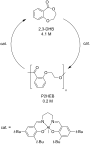
Scheme 17: Polymerisation–depolymerisation cycle of 2,3-HDB.

Scheme 18: Hydrogenative depolymerisation of PBPAC by molecular Ru catalysts.

Scheme 19: Catalytic hydrolysis (top), alcoholysis (middle) and aminolysis (bottom) reactions of PBPAC.

Scheme 20: Hydrogenative depolymerisation of PPC (top) and PEC (bottom) by molecular Ru catalysts.
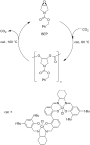
Scheme 21: Polymerisation-depolymerisation cycle of BEP.

Scheme 22: Hydrogenolysis of polyamides using soluble Ru catalysts.

Scheme 23: Catalytic depolymerisation of epoxy resin/carbon fibres composite.

Scheme 24: Depolymerisation of polyethers with metal salt catalysts and acyl chlorides.
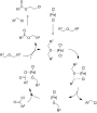
Scheme 25: Proposed mechanism for the iron-catalysed depolymerisation reaction of polyethers. Adapted with per...
Amino- and polyaminophthalazin-1(2H)-ones: synthesis, coordination properties, and biological activity
- Zbigniew Malinowski,
- Emilia Fornal,
- Agata Sumara,
- Renata Kontek,
- Karol Bukowski,
- Beata Pasternak,
- Dariusz Sroczyński,
- Joachim Kusz,
- Magdalena Małecka and
- Monika Nowak
Beilstein J. Org. Chem. 2021, 17, 558–568, doi:10.3762/bjoc.17.50
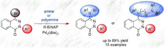
- -aminophthalazinones, we decided to investigate how these compounds behave towards Cu(II) ions. For testing, we chose the derivatives of ethylenediamine 6d, N-phenylpyridin-2-amine 5i, and additionally the pyridin-2-yl derivative 7 (Figure 3). Compound 7 was synthesized according to the method described by us [43
- ]. All selected compounds (Figure 3) contain some specific structural elements (e.g., an ethylenediamine moiety, similarity to bipyridyl or even to isocyclam skeleton) allowing them to act as ligands and form complexes. In our tests, we hoped that putting in the 4-position of the skeleton a substituent

Graphical Abstract

Figure 1: Structure of biologically active phthalazine derivatives.

Scheme 1: Synthetic route to aminophthalazinones 5 and 6.
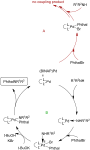
Figure 2: Proposed catalytic cycles for the amination of 4-bromophthalazinones of type 3 (Phthal: phthalazino...
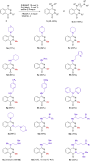
Scheme 2: Synthesis of 4-amino- and 4-polyaminophthalazinones 5 and 6 (the yields refer to the isolated compo...

Figure 3: The phthalazinone derivatives that were used to test the complexation of Cu(II) ions.
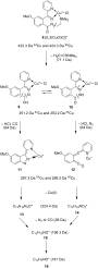
Scheme 3: The proposal of the fragmentation pathway of the Cu(II) complex with compound 7.

Figure 4: Structure of complex 17.

Figure 5: Molecular structure of complex 17 with atom numbering scheme. The anisotropic displacement paramete...
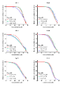
Figure 6: Determination of relative cell viability (% of control) in different cell lines (HT-29; PC-3 and L-...

Figure 7: Cytotoxic properties of the phthalazinone derivatives expressed as IC50 after 72 h of cell treatmen...
Au(III) complexes with tetradentate-cyclam-based ligands
- Ann Christin Reiersølmoen,
- Thomas N. Solvi and
- Anne Fiksdahl
Beilstein J. Org. Chem. 2021, 17, 186–192, doi:10.3762/bjoc.17.18
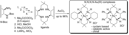
- -tetraazacyclotetradecane), cyclen (1,4,7,10-tetraazacyclododecane)), ethylenediamine and triethylenetetraamine derivatives. Studies of Au(III)-cyclam modified complexes have been limited to arylated [16] or polymer-bound cyclams for selective uptake of Au(III) from water [17] as well as X-ray crystal structures [18][19

Graphical Abstract

Scheme 1: Synthetic protocols for the preparation of potential ligands 1–4.

Scheme 2: Reduction of diamides 1a,b and tetraamides 2a,b.

Scheme 3: Au(III) coordination conditions for ligands 5a,b and 6a,b. Coordination of 5b was unsuccessful.

Figure 1: 1H NMR study of the formation of complex 6a-Au(III) by AuCl3 coordination to ligand 6a.
Recent progress in the synthesis of homotropane alkaloids adaline, euphococcinine and N-methyleuphococcinine
- Dimas J. P. Lima,
- Antonio E. G. Santana,
- Michael A. Birkett and
- Ricardo S. Porto
Beilstein J. Org. Chem. 2021, 17, 28–41, doi:10.3762/bjoc.17.4
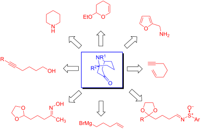
- . After the treatment of (−)-46 with the lithium acetylide ethylenediamine complex in THF, a nucleophilic alkynylation occurred, with a reversal of configuration in the reaction center. Then, removal of the 1-(2-hydroxyphenyl)ethyl group via cleavage of the C–N bond, leading to (6S)-ethynylpiperidine
- occurred by removing the TBDMS and formyl (CHO) groups via treatment with TBAF in dry THF and lithium–ethylenediamine complex, respectively. Finally, the resulting alcohol (+)-56 was oxidized in the presence of PCC to provide (−)-adaline (1). In this work, the quaternary center was successfully generated

Graphical Abstract

Figure 1: Homotropane (azabicyclononane) systems.

Figure 2: Alkaloids (−)-adaline (1), (+)-euphococcinine (2) and (+)-N-methyleuphococcinine (3).

Scheme 1: Synthetic strategies before 1995.

Scheme 2: Synthesis (±)-adaline (1) and (±)-euphococcinine (2). Reagents and conditions: i) 1. dihydropyran, ...

Scheme 3: Synthesis (+)-euphococcinine (2). Reagents and conditions: i) H2O2, SeO2 (cat), acetone, rt, 88%; i...

Scheme 4: Synthesis (+)-euphococcinine (2). Reagents and conditions: i) 2,4-bis(4-phenoxyphenyl)-1,3-dithia-2...

Scheme 5: Synthesis of (±)-euphococcinine precursor (±)-42. Reagents and conditions: i) Bu3SnH, AIBN, toluene...

Scheme 6: Synthesis of (−)-adaline (1). Reagents and conditions: i) LiH2NBH3, THF, 40 °C, 88%; ii) TPAP, NMO,...

Scheme 7: Synthesis of (−)-adaline (1) and (−)-euphococcinine (2). Reagents and conditions: i) 1. BuLi, t-BuO...

Scheme 8: Synthesis of (−)-adaline (1). Reagents and conditions: i) Ref. [52]; ii) Et3N, TBDMSOTf, CH2Cl2, 0 °C t...

Scheme 9: Synthesis of (+)-euphococcinine (2). Reagents and conditions: i) 1. Cp2ZrCl2,AlMe3, CH2Cl2; 2. p-me...

Scheme 10: Synthesis of (−)-adaline 1. Reagents and conditions: i) 1. CuBr.DMS, Et2O/DMS, -42 ºC; 2. 1-heptyne...

Scheme 11: Synthesis of (−)-euphococcinine (2) and (−)-adaline (1). Reagents and conditions: i) 102, KHMDS, Et2...

Scheme 12: Synthesis of N-methyleuphococcinine 3. Reagents and conditions: i) 108 (1.5 equiv), 3,5-di-F-C6H3B(...
Thermodynamic and electrochemical study of tailor-made crown ethers for redox-switchable (pseudo)rotaxanes
- Henrik Hupatz,
- Marius Gaedke,
- Hendrik V. Schröder,
- Julia Beerhues,
- Arto Valkonen,
- Fabian Klautzsch,
- Sebastian Müller,
- Felix Witte,
- Kari Rissanen,
- Biprajit Sarkar and
- Christoph A. Schalley
Beilstein J. Org. Chem. 2020, 16, 2576–2588, doi:10.3762/bjoc.16.209
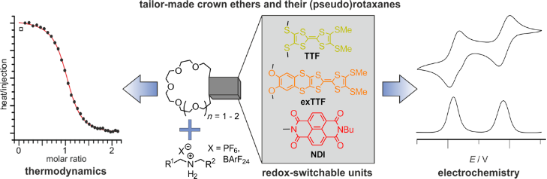
- connection to the crown ether core, and in NDIC7, a more flexible ethylenediamine linker is used. Crown ether synthesis and crystal structures With respect to the synthesis of previously reported TTFC8 and exTTFC8 [35][37], we synthesized the novel 21-crown-7 analogs following a similar synthetic route

Graphical Abstract

Figure 1: Structures of the compounds used in this study: a) crown-8 analogs; b) crown-7 analogs; c) secondar...
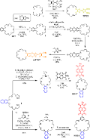
Scheme 1: Schematic representation of synthetic routes towards TTFC7, exTTFC7, NDIC7, and NDIC8.

Figure 2: Solid-state structures of a) exTTFC7 (CH3CN molecule omitted for clarity), b) NDIC7 (CH3CN molecule...

Figure 3: a) Synthesis of the [2]rotaxane NDIRot. b) Stacked 1H NMR spectra (700 MHz, CDCl3, 298 K) of NDIC8 ...

Figure 4: UV–vis–NIR spectra obtained by spectroelectrochemical measurements (0.1 M n-Bu4PF6, CH2Cl2/CH3CN 1:...
Naphthalene diimide bis-guanidinio-carbonyl-pyrrole as a pH-switchable threading DNA intercalator
- Poulami Jana,
- Filip Šupljika,
- Carsten Schmuck and
- Ivo Piantanida
Beilstein J. Org. Chem. 2020, 16, 2201–2211, doi:10.3762/bjoc.16.185
- ethylenediamine (2 equiv) was added to 1,4,5,8-naphthalenetetracarboxylic dianhydride (1, 1 equiv) in dry DMF. The mixture was stirred for 15 h at 90 °C. The crude product was extracted into the organic (chloroform) layer and concentrated under vacuum. The crude product was further purified by column
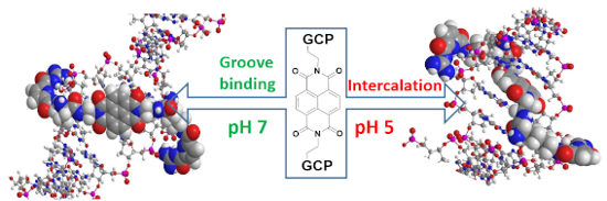
- adjacent amino groups (pH 7, green) and decorated by two GCP arms protonated at pH 5 (red; pH-switchable DNA groove binders). Synthesis of compound 4. Conditions: a) mono-N-Boc-ethylenediamine, DMF, 90 °C; b) i) trifluoroacetic acid (TFA)/CH2Cl2 1:1, ii) Fmoc-Lys(Boc)-OH, DIPEA, HCTU; c) i) TFA/CH2Cl2 1:1

Graphical Abstract

Scheme 1: DNA-targeting roles of the structural components incorporated in the design of the novel small mole...

Scheme 2: Synthesis of compound 4. Conditions: a) mono-N-Boc-ethylenediamine, DMF, 90 °C; b) i) trifluoroacet...
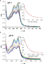
Figure 1: UV–vis titrations of compound 4 (c = 1.0 × 10⁻⁶ M), with ct-DNA at pH 7.0 (a) and at pH 5 (b). Inse...

Figure 2: a) CD titration of ct-DNA (c = 3.0 × 10⁻⁵ M) with compound 4 at pH 7.0 (Na cacodylate buffer, I = 0...
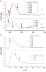
Figure 3: CD titration of poly(rA)–poly(rU) (c = 3.0 × 10⁻⁵ M) with compound 4 at a) pH 7.0 (Na cacodylate bu...

Figure 4: CD titration of ds-DNAs (c = 3.0 × 10⁻⁵ M) with 4 for ratio r[4]/ [DNA] = 0.4. Done at pH 5.0 (Na c...

Figure 5: ITC experiments of poly(dAdT)–poly(dAdT) (c = 5.0 × 10⁻⁵ M) titrated with compound 4. Dots represen...

Figure 6: AFM image of a) ct-DNA showing a fibre-like structure with a length of several micrometres; b) upon...
Recent advances in Cu-catalyzed C(sp3)–Si and C(sp3)–B bond formation
- Balaram S. Takale,
- Ruchita R. Thakore,
- Elham Etemadi-Davan and
- Bruce H. Lipshutz
Beilstein J. Org. Chem. 2020, 16, 691–737, doi:10.3762/bjoc.16.67
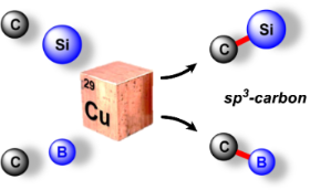
- co-workers [39] used a comparatively simple ligand to perform asymmetric silylations of imines. Different ethylenediamine-based ligands (L3–L5) were screened from which L3 proved to give even better yields and ees (Scheme 13). The use of this ligand was explored with other substrates 56 and found to

Graphical Abstract

Scheme 1: Pharmaceuticals possessing a silicon or boron atom.

Scheme 2: The first Cu-catalyzed C(sp3)–Si bond formation.

Scheme 3: Conversion of benzylic phosphate 6 to the corresponding silane.

Scheme 4: Conversion of alkyl triflates to alkylsilanes.

Scheme 5: Conversion of secondary alkyl triflates to alkylsilanes.

Scheme 6: Conversion of alkyl iodides to alkylsilanes.

Scheme 7: Trapping of intermediate radical through cascade reaction.

Scheme 8: Radical pathway for conversion of alkyl iodides to alkylsilanes.

Scheme 9: Conversion of alkyl ester of N-hydroxyphthalimide to alkylsilanes.

Scheme 10: Conversion of gem-dibromides to bis-silylalkanes.

Scheme 11: Conversion of imines to α-silylated amines (A) and the reaction pathway (B).

Scheme 12: Conversion of N-tosylimines to α-silylated amines.

Scheme 13: Screening of diamine ligands.

Scheme 14: Conversion of N-tert-butylsulfonylimines to α-silylated amines.

Scheme 15: Conversion of aldimines to nonracemic α-silylated amines.

Scheme 16: Conversion of N-tosylimines to α-silylated amines.

Scheme 17: Reaction pathway [A] and conversion of aldehydes to α-silylated alcohols [B].

Scheme 18: Conversion of aldehydes to benzhydryl silyl ethers.

Scheme 19: Conversion of ketones to 1,2-diols (A) and conversion of imines to 1,2-amino alcohols (B).

Scheme 20: Ligand screening (A) and conversion of aldehydes to α-silylated alcohols (B).

Scheme 21: Conversion of aldehydes to α-silylated alcohols.

Scheme 22: 1,4-Additions to α,β-unsaturated ketones.

Scheme 23: 1,4-Additions to unsaturated ketones to give β-silylated derivatives.

Scheme 24: Additions onto α,β-unsaturated lactones to give β-silylated lactones.

Scheme 25: Conversion of α,β-unsaturated to β-silylated lactams.

Scheme 26: Conversion of N-arylacrylamides to silylated oxindoles.

Scheme 27: Conversion of α,β-unsaturated carbonyl compounds to silylated tert-butylperoxides.

Scheme 28: Catalytic cycle for Cu(I) catalyzed α,β-unsaturated compounds.

Scheme 29: Conversion of p-quinone methides to benzylic silanes.

Scheme 30: Conversion of α,β-unsaturated ketimines to regio- and stereocontrolled allylic silanes.

Scheme 31: Conversion of α,β-unsaturated ketimines to enantioenriched allylic silanes.

Scheme 32: Regioselective conversion of dienedioates to allylic silanes.

Scheme 33: Conversion of alkenyl-substituted azaarenes to β-silylated adducts.

Scheme 34: Conversion of conjugated benzoxazoles to enantioenriched β-silylated adducts.

Scheme 35: Conversion of α,β-unsaturated carbonyl indoles to α-silylated N-alkylated indoles.

Scheme 36: Conversion of β-amidoacrylates to α-aminosilanes.

Scheme 37: Conversion of α,β-unsaturated ketones to enantioenriched β-silylated ketones, nitriles, and nitro d...

Scheme 38: Regio-divergent silacarboxylation of allenes.

Scheme 39: Silylation of diazocarbonyl compounds, (A) asymmetric and (B) racemic.

Scheme 40: Enantioselective hydrosilylation of alkenes.

Scheme 41: Conversion of 3-acylindoles to indolino-silanes.

Scheme 42: Proposed mechanism for the silylation of 3-acylindoles.

Scheme 43: Silyation of N-chlorosulfonamides.

Scheme 44: Conversion of acyl silanes to α-silyl alcohols.

Scheme 45: Conversion of N-tosylaziridines to β-silylated N-tosylamines.

Scheme 46: Conversion of N-tosylaziridines to silylated N-tosylamines.

Scheme 47: Conversion of 3,3-disubstituted cyclopropenes to silylated cyclopropanes.

Scheme 48: Conversion of conjugated enynes to 1,3-bis(silyl)propenes.

Scheme 49: Proposed sequence for the Cu-catalyzed borylation of substituted alkenes.

Scheme 50: Cu-catalyzed synthesis of nonracemic allylic boronates.

Scheme 51: Cu–NHC catalyzed synthesis of α-substituted allylboronates.
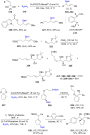
Scheme 52: Synthesis of α-chiral (γ-alkoxyallyl)boronates.

Scheme 53: Cu-mediated formation of nonracemic cis- or trans- 2-substituted cyclopropylboronates.

Scheme 54: Cu-catalyzed synthesis of γ,γ-gem-difluoroallylboronates.

Scheme 55: Cu-catalyzed hydrofunctionalization of internal alkenes and vinylarenes.

Scheme 56: Cu-catalyzed Markovnikov and anti-Markovnikov borylation of alkenes.

Scheme 57: Cu-catalyzed borylation/ortho-cyanation/Cope rearrangement.
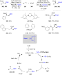
Scheme 58: Borylfluoromethylation of alkenes.

Scheme 59: Cu-catalyzed synthesis of tertiary nonracemic alcohols.

Scheme 60: Synthesis of densely functionalized and synthetically versatile 1,2- or 4,3-borocyanated 1,3-butadi...

Scheme 61: Cu-catalyzed trifunctionalization of allenes.

Scheme 62: Cu-catalyzed selective arylborylation of arenes.

Scheme 63: Asymmetric borylative coupling between styrenes and imines.

Scheme 64: Regio-divergent aminoboration of unactivated terminal alkenes.

Scheme 65: Cu-catalyzed 1,4-borylation of α,β-unsaturated ketones.

Scheme 66: Cu-catalyzed protodeboronation of α,β-unsaturated ketones.

Scheme 67: Cu-catalyzed β-borylation of α,β-unsaturated imines.

Scheme 68: Cu-catalyzed synthesis of β-trifluoroborato carbonyl compounds.

Scheme 69: Asymmetric 1,4-borylation of α,β-unsaturated carbonyl compounds.

Scheme 70: Cu-catalyzed ACB and ACA reactions of α,β-unsaturated 2-acyl-N-methylimidazoles.

Scheme 71: Cu-catalyzed diborylation of aldehydes.

Scheme 72: Umpolung pathway for chiral, nonracemic tertiary alcohol synthesis (top) and proposed mechanism for...

Scheme 73: Cu-catalyzed synthesis of α-hydroxyboronates.

Scheme 74: Cu-catalyzed borylation of ketones.

Scheme 75: Cu-catalyzed borylation of unactivated alkyl halides.

Scheme 76: Cu-catalyzed borylation of allylic difluorides.

Scheme 77: Cu-catalyzed borylation of cyclic and acyclic alkyl halides.

Scheme 78: Cu-catalyzed borylation of unactivated alkyl chlorides and bromides.

Scheme 79: Cu-catalyzed decarboxylative borylation of carboxylic acids.
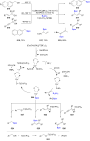
Scheme 80: Cu-catalyzed borylation of benzylic, allylic, and propargylic alcohols.
Chemical synthesis of the pentasaccharide repeating unit of the O-specific polysaccharide from Escherichia coli O132 in the form of its 2-aminoethyl glycoside
- Debasish Pal and
- Balaram Mukhopadhyay
Beilstein J. Org. Chem. 2019, 15, 2563–2568, doi:10.3762/bjoc.15.249
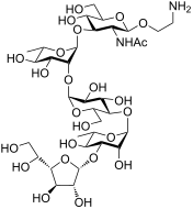
- the target molecule. First, the phthalimido group was removed using ethylenediamine [26] followed by acetylation with Ac2O in the presence of pyridine [27] to furnish the desired acetamido functionality. Next, the benzylidene group was hydrolyzed using 80% AcOH at 80 ºC [28]. Further, Zemplén de-O

Graphical Abstract

Figure 1: Structure of the target pentasaccharide repeating unit in the form of its 2-aminoethyl glycoside.
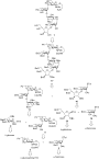
Figure 2: Retrosynthetic analysis for the synthesis of the target pentasaccharide 1.

Scheme 1: Synthesis of the disaccharide acceptor 5.

Scheme 2: Synthesis of the trisaccharide acceptor 11.

Scheme 3: Synthesis of the non-reducing end disaccharides (16a and 16b).

Scheme 4: Synthesis of the target pentasaccharide 1.
1,2,3,4-Tetrahydro-1,4,5,8-tetraazaanthracene revisited: properties and structural evidence of aromaticity loss
- Arnault Heynderickx,
- Sébastien Nénon,
- Olivier Siri,
- Vladimir Lokshin and
- Vladimir Khodorkovsky
Beilstein J. Org. Chem. 2019, 15, 2059–2068, doi:10.3762/bjoc.15.203
- ]. A strongly fluorescent compound, 3, has been isolated from the reaction of ethylenediamine with noradrenaline, 2-methylnoradrenaline, adrenolone, 3,4-dihydroxymandelic acid or catechol [8]. The reaction with 2,5-dihydroxy-p-benzoquinone (4) under a stream of air affording 3 in 50% yield was proposed
- THTAA Derivative 3 was prepared from 2,5-dihydroxy-p-benzoquinone and ethylenediamine as brownish-yellow solid according to the recommended procedure (Scheme 1) [8]. Crystallization from butyl acetate produced yellow crystals of THTAA (3) in about 50% yield, still slightly brownish, along with the

Graphical Abstract

Figure 1: Quinoxaline derivatives 1–3.

Scheme 1: Synthesis of THTTA (3).

Scheme 2: Protonation, alkylation and acylation of 3.

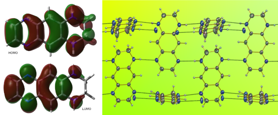
Figure 2: The ORTEP view of 3. Torsion angles within the benzene ring are given in red.

Figure 3: The ORTEP view of 6a. Torsion angles within the benzene ring are given in red.

Figure 4: The ORTEP view of 7a (the iodine counter anion has been omitted for clarity). Torsion angles within...
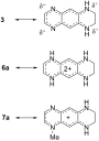
Scheme 3: Charge transfer and delocalization within 3 and its diprotonated (6a) and monomethylated (7a) deriv...

Figure 5: Normalized absorption spectra of 3 in: toluene (black), acetone (blue), ethanol (green), water (red...

Figure 6: Protonation of 3 in ethanol. Two isosbestic points (IBP) are indicated by arrows.

Figure 7: Absorption spectra of 7a (blue) and 8 (red) in ethanol.

Figure 8: Absorption spectra of 10a (black), 10b (red). Solid curves: in toluene, dashed curves: in acetone.

Figure 9: View of the supramolecular array generated by 3 in the solid state. Color coding: nitrogen, blue; c...

Figure 10: View of the supramolecular array generated by 6a in the solid state. Color coding: nitrogen, blue; ...

Figure 11: View of the supramolecular array generated by 7a in the solid state. Color coding: nitrogen, blue; ...
Mechanochemistry of supramolecules
- Anima Bose and
- Prasenjit Mal
Beilstein J. Org. Chem. 2019, 15, 881–900, doi:10.3762/bjoc.15.86
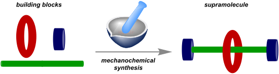
- ) and ethylenediamine (5). Subsequently, to the same pot appropriate metals were added to obtain the respective complexes 7 [55]. In 2002, Otera and co-workers reported the formation of some supramolecular self-assembled structures which was found to be faster under solvent-free mechanochemical

Graphical Abstract

Figure 1: A generalized overview of coordination-driven self-assembly.

Figure 2: Examples of self-assembly or self-sorting and subsequent substitution.

Figure 3: Synthesis of salen-type ligand followed by metal-complex formation in the same pot [55].

Figure 4: Otera’s solvent-free approach by which the formation of self-assembled supramolecules could be acce...

Figure 5: Synthesis of a Pd-based metalla-supramolecular assembly through mechanochemical activation for C–H-...

Figure 6: a) Schematic representation for the construction of a [2]rotaxane. b) Chiu’s ball-milling approach ...

Figure 7: Mechanochemical synthesis of the smallest [2]rotaxane.

Figure 8: Solvent-free mechanochemical synthesis of pillar[5]arene-containing [2]rotaxanes [61].

Figure 9: Mechanochemical liquid-assisted one-pot two-step synthesis of [2]rotaxanes under high-speed vibrati...

Figure 10: Mechanochemical (ball-milling) synthesis of molecular sphere-like nanostructures [63].

Figure 11: High-speed vibration milling (HSVM) synthesis of boronic ester cages of type 22 [64].

Figure 12: Mechanochemical synthesis of borasiloxane-based macrocycles.

Figure 13: Mechanochemical synthesis of 2-dimensional aromatic polyamides.

Figure 14: Nitschke’s tetrahedral Fe(II) cage 25.

Figure 15: Mechanochemical one-pot synthesis of the 22-component [Fe4(AD2)6]4− 26, 11-component [Fe2(BD2)3]2− ...

Figure 16: a) Subcomponent synthesis of catalyst and reagent and b) followed by multicomponent reaction for sy...

Figure 17: A dynamic combinatorial library (DCL) could be self-sorted to two distinct products.

Figure 18: Mechanochemical synthesis of dynamic covalent systems via thermodynamic control.

Figure 19: Preferential formation of hexamer 33 under mechanochemical shaking via non-covalent interactions of...

Figure 20: Anion templated mechanochemical synthesis of macrocycles cycHC[n] by validating the concept of dyna...

Figure 21: Hydrogen-bond-assisted [2 + 2]-cycloaddition reaction through solid-state grinding. Hydrogen-bond d...

Figure 22: Formation of the cage and encapsulation of [2.2]paracyclophane guest molecule in the cage was done ...

Figure 23: Formation of the 1:1 complex C60–tert-butylcalix[4]azulene through mortar and pestle grinding of th...

Figure 24: Formation of a 2:2 complex between the supramolecular catalyst and the reagent in the transition st...

Figure 25: Halogen-bonded co-crystals via a) I···P, b) I···As, and c) I···Sb bonds [112].

Figure 26: Transformation of contact-explosive primary amines and iodine(III) into a successful chemical react...

Figure 27: Undirected C–H functionalization by using the acidic hydrogen to control basicity of the amines [114]. a...